Description
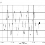
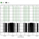
SPICE simulation of a static inverter with voltage regulation and current limit. The bit pattern is stored in the PWL state code file 64s.txt. A square wave at V(10) is filtered to create a ramp at the node V(ramp). B2 compares the combined outputs of the softstart, voltage error amp and current amplifier to the ramp, creating a 100kHz variable duty cycle that modulates the full bridge. D5, D6 and core X1 provide shoot thru protection for the Mosfets, while L3, C1 and C2 provide the output filtering to reconstruct the sine wave. X3 and the associated circuitry provides the current limit while L6 is a winding of the inverter transformer, used for voltage regulation.


Reviews
There are no reviews yet.