Proteus Video tutorials

Proteus Video tutorials

Welcome to the Proteus Video Tutorials page, an informative destination crafted to provide you with a seamless and insightful exploration of the inherent capabilities within the Proteus simulation software. Within this dedicated space, you will embark on a journey through a curated selection of YouTube videos, each chosen to present a comprehensive panorama of Proteus’s rich feature set.

These Video tutorials span a diverse array of functionalities, encompassing everything from the analog circuit simulation to the dynamic landscape of digital circuit emulation. A particularly distinctive facet of this tutorial collection is its coverage of circuits featuring programmable microcontrollers, showcasing an important attribute of the Proteus software.

By engaging with the Proteus Video Tutorials, you will effortlessly acquire a comprehensive understanding of the multifaceted world of circuit design and simulation, all facilitated by this advanced software. Whether you’re a novice seeking an introduction to circuitry or a seasoned designer seeking to delve into the depths of intricate PCB layout, these tutorials are designed to empower and equip you with the skills you need.

About Proteus: Proteus is a robust and versatile simulation software widely acclaimed by electronics enthusiasts, students, and professionals alike. Renowned for its user-friendly interface and comprehensive toolset, Proteus facilitates the design, simulation, and testing of circuits in a virtual environment. Its prowess extends to both analog and digital circuitry, enabling accurate analysis and optimization before real-world implementation. The integration of microcontroller simulation elevates Proteus to a league of its own, providing a platform for exploring the functionality of embedded systems.

Proteus offers an expansive array of features that cater to various skill levels and requirements. The Proteus Video Tutorials page is your gateway to unraveling the great potential this software holds, guiding you through its intricacies and empowering you to bring your circuit designs to life with confidence and precision.

For a detailed walkthrough on creating and simulating your initial circuit using NI Multisim, you can consult this article.


DC Machine and Motor Speed Drives Course with Proteus!!


TopicVideo
How to simulate a simple circuit with Proteus
How to create a component symbol in Proteus
How to perform a Time domain analysis in Proteus
Security Alarm System Simulation
Buck Boost Converter Simulation
Logic Gates Proteus Simulation
Microcontroller Simulation with Proteus
Arduino Proteus Simulation
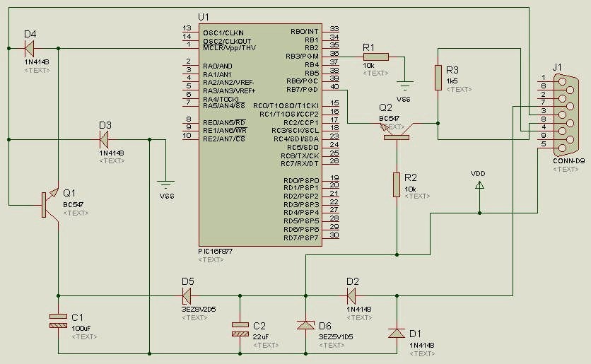
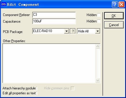
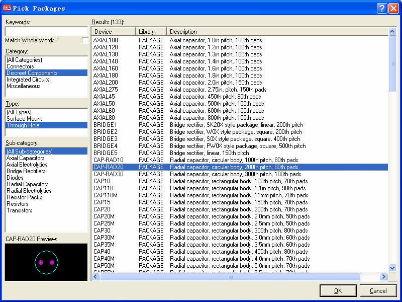
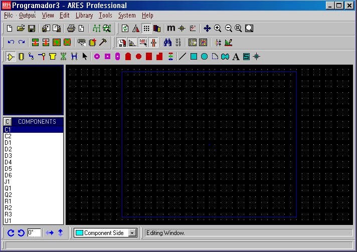
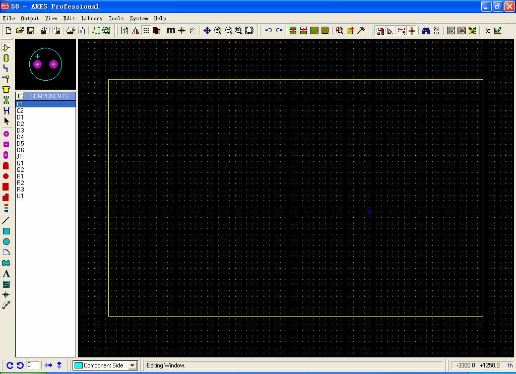
How to design a circuit board layout with Proteus ARES


Digital Electronics for Beginner’s:- Mastering with PROTEUS!!

Getting Started with Proteus PCB

In this article, we will examine the essential procedure for moving from a complete circuit diagram, in this case featuring a PIC microcontroller in Proteus schematic, to its associated PCB project in Proteus PCB. This step by step guide aims to provide a systematic and informative guide, to facilitate the seamless conversion of your electronic circuits into tangible and functional prototypes through the utilization of Proteus PCB

Let’s commence with this comprehensive Proteus schematic.


Proteus_page117_image1


this microcontroller circuit has the following components:

4 diodes 1N4148

2 NPN transistors BC547

2 electrolitic capacitors CAP-ELEC

2 zener diodes a 3EZ8V2D5 and a 3EZ5V1D5

3 resistors RES

a connector D-type 9 pin female CONN-D9

a PIC microcontroller PIC16F877

The PIC16F877 features two concealed pins, VDD and VSS. The VDD pin should be designated as ‘POWER,’ and the VSS pin should be assigned as ‘GROUND.’ When incorporating a component in Proteus Schematic, certain components are preconfigured with a corresponding PCB footprint, while others may not possess an associated PCB footprint and necessitate manual addition. In such instances, it is imperative to manually include the appropriate footprint, as illustrated in the ‘CAP-ELEC’ example below:


Open the Properties dialog box for the CAP-ELEC component. Click the “?” Button (in the latest versions the binoculars icon) to open the PCB package selection dialog


Proteus_page118_image1


Select an appropriate PCB footprint, and then click ‘OK’ to confirm your choice. Proceed to select PCB footprints for all the components. Next, open the Netlist Compiler by navigating to the ‘Tools’ menu within Isis Proteus (Tools -> Netlist Compiler). A settings dialog box will appear; please retain the default settings and click ‘OK’ to generate the netlist file. Once the file is generated, access ARES software by selecting ‘Tools -> Netlist to ARES’ from the ‘Tools’ menu. Alternatively, you can utilize the corresponding button on the toolbar to perform this operation.


Proteus_page119_image3


Note: in the latest versions of Proteus it is sufficient to click on the PCB Layout icon:


DC Machine and Motor Speed Drives Course with Proteus!!


As we can see, the workspace is currently empty, and our intention is to utilize all the elements listed on the left.

Before proceeding with component placement, it is essential to create a border. To achieve this, we utilize the ‘2D Graphics Box Mode’ button to draw the border:


Prior to initiating the drawing procedure, it is necessary to make a color selection. Given the border’s nature, we have chosen the color yellow (Board Edge), as discernible within the settings tool situated at the lower section of the main window:


Click within the workspace, hold down the left mouse button, drag the cursor to define a rectangle of suitable dimensions, and then release the mouse button.

If you wish to make adjustments to the board’s size at a later stage, you can follow these steps: Click on the ‘2D Graphics Box’ rectangular icon once more, right-click on any of the board’s corners to reveal a control point, and then drag this control point to resize the board. To return to the components placement view, simply click the icon located below:


To populate the board with components, please follow these steps. For an overall perspective, press the ‘F8’ key. The outcome will be as follows:


Proteus_page120_image1