Public info about the author: BassMaster
- Profile

-

This high-crossover frequency buck converter includes a conversion delay that affects the final phase margin. The design uses an op amp-based type 3 compensation circuit.
- Free
- Intermediate
- 11-20
- ICAP/4
- 8.9.11+
- Yes
-
-

This circuit lets you simulate the effects of the phase lag brought by a cascaded RC network. Actually, this is a closed-loop system. By changing the open-loop phase margin, you affect the closed-loop quality factor.
- Free
- Simple
- <10
- ICAP/4
- 8.9.11+
- No
-

-

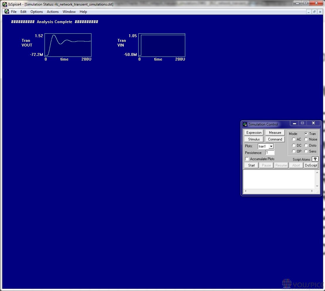
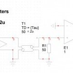
quality factor, response speed, RLC network. You specify the quality factor and the software computes the series resistance accordingly. The transient response shows how the quality factor affects overshoots and response speed.
- Free
- Very simple
- <10
- ICAP/4
- 8.9.11+
- No
-
-

This is a design sheet for those who want to design the compensation circuit of a voltage-mode buck converter. The design includes a buck PWM switch model and an op amp-based type 3 compensator. Test the ac response but also the transient response by changing the simulation templates on the fly.
- Free
- Intermediate
- 11-20
- ICAP/4
- 8.9.11+
- Yes
-

-
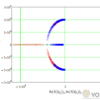
Root locus also called Evans locus plots are shown here in a simple Mathcad sheet. This simple Mathcad sheet lets you plot how the roots of a 2-nd order circuit splits as the quality factor increases from a weak value to infinity. Watch the pole splitting for Q = 0.5 and lose their real portion (no more damping) as Q reaches infinity.
- Free
- Simple
- <10
- Mathcad
- 15+
- Yes
-