Home › Forums › General Electronics › Transistors › CMOS in Pspice
- This topic is empty.
-
AuthorPosts
-
December 14, 2012 at 7:54 am #16290
 hurhassanGuestDear all,I want to design a cmos circuit (pmos and nmos) by using PSpice 16.5, what type of transistor i can use? How can I edit the models in PSpice 16.5 such as Kp, Vth, L,W.RegardsDecember 19, 2012 at 6:33 am #16385
Hi hurhassan
working in PSpice with customizable CMOS model is simple. I use 16.3 version, but it’s the same for 16.5.
Create a new project
for a NMOS take MbreakN from BREAKOUT library and place on the layout
(for a PMOS take a MbreakP)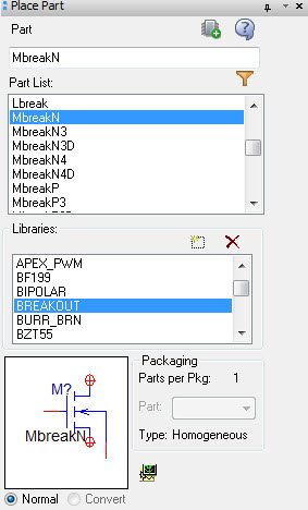
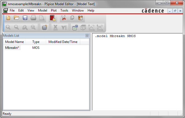
Select it, right click, “Edit PSpice model”, choose PSpice A/D, and then this window pops up
Excellent libraries for CMOS are available, for example you can use the cmosedu_models
by Jacob Baker. This a library for LTspice, Fortunately, the two syntaxes, with few exceptions, are compatible.To model a NMOS long channel, with 1 um minimum drawn channel length, copy the first .model statement and paste in the editor window, save
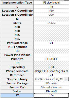
At this point right click on the CMOS, choose Edit Properties.Edit L 1u, and for example, W=10u
to perform a DC sweep analysis, draw this simple circuit
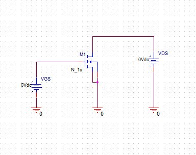
Add a netsted DC sweep simulation, and run
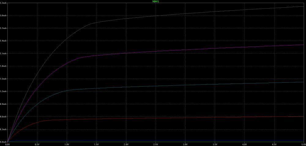
this is the PSpice simulation result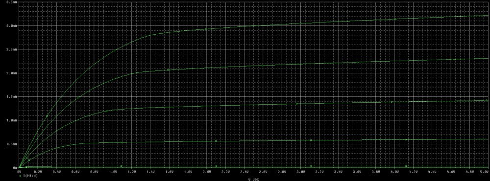
that obviously is the same of LTspice
Attachments:
You must be logged in to view attached files.May 14, 2015 at 8:28 am #16480poynt99
GuestDoes anyone know PSpice Model Editor well?
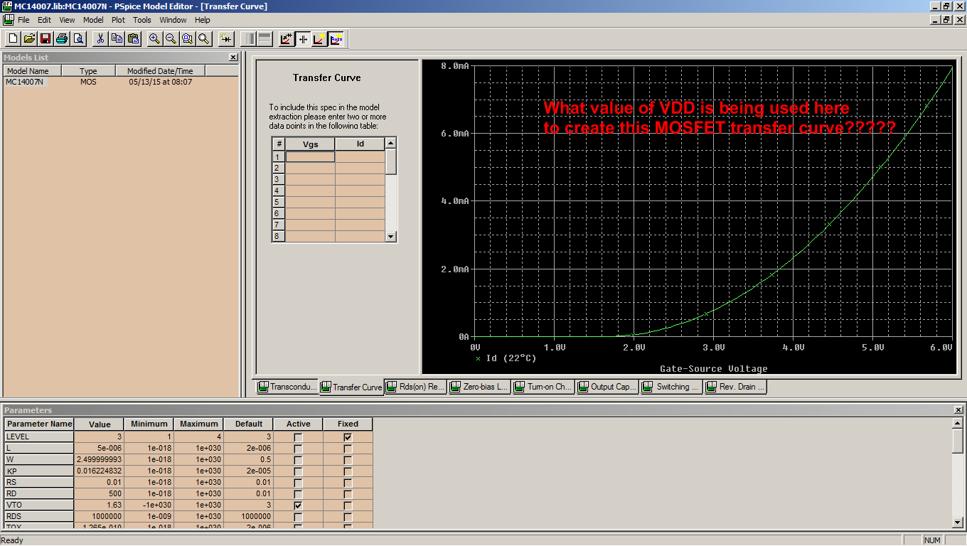
The background to the question, when you are creating a new model (MOSFET) from a data sheet, Model Editor (ME) has a window with the LEVEL 3 parameters at the bottom, and a window in the top right with several tabs with curves; Transconductance, Transfer Curve, Rds(on), Rev. Drain Current etc.. When producing curves, there are always 1 or 2 of 3 parameters that are swept, while one is held constant. For example, with a transfer curve, VDD is held constant, Vgs is swept, and Id is measured, and Vgs vs. Id is plotted.
My question is this: ME does not allow you to enter a value for the fixed parameter, VDD in my example above. If it does have a field somewhere, I have not been able to find it. The same goes for all the other tabs I mentioned above, there is no where to enter the fixed value. So while trying to match the curves with actual data sheet curves or actual bench-swept curves, how can I do it if I don’t know what I am matching to?
See followin picture
Thanks,
.99August 25, 2015 at 11:43 am #16483In practice there is little match of empirical parameters in modern models (level 3 was the last one).
The best bet is to edit the model name in the transistor symbol and provide the model in the .lib later inluded in the spice command file. Hopefully the vendor can provide this model file. For a simple empirical model some basic parameters can be extracted. I believe Baker’s book has some pointers on doing this. Vt can be defined as the Vgs where you get 1uA of current, or 0.1uA, as you prefer, under the particular conditions of Vdd, Temp, etc. gm is roughly the derivative of the id curves when the transistor is operating in saturation, as Vgs is changed. Lambda can be derived from the x-axis intercept (as the Early voltage for a bjt). Gamma is a bit more difficult to derive, but it’s effect is inverse quadratic anyway. -
AuthorPosts
- You must be logged in to reply to this topic.
