Home › Forums › Audio Circuits › Di Box
- This topic is empty.
-
AuthorPosts
-
July 5, 2012 at 5:42 am #16282
Hi Everyone,
I’m very new to electronics in general and found your site to be the most informative when it comes to simulations!
My background as a sound engineer has drawn me into this world and I’d really appretiate any help any one can give me. As a small project, I’ve decided to build one of these:

A figured a good place to start would be try and simulate the circuit with LTSpice. Could someone take a look at the asc file I’ve attached and help me with getting this simulation to work?
The challenges I’m having are mainly around adapting the input and output jacks so as to simulate a signal being passed through the circuit as well as simulating the specified transformer and the 48v power supply which would be a voltage source typically originating from a mixing desk.
Thanks in advance!
July 7, 2012 at 12:54 pm #16373Hi David,
it seems a very good project. In your schematic there are several mismatches respect to the original project.The transistor Q2 is a PNP, not a NPN, I’ve uploaded the transistors library bjtdibox.lib to add in
..LTCLTspiceIVlibsub directory. Inside there are spice models of BC550C and the PNP BC560C.
I’ve added a directive to include the library in the new .asc file.The DI-box project use a 5:1 transformer,
this ratio normally refers to turns and then voltages ratio, not to inductances ratio, and in your schematic are reversed. If the turns ratio is 5:1 the inductances ratio must be 25:1, for example L1=250H and L2=10H.
Now you should be on the right track, let us know about your results and if you like share them with the community.cheers
July 10, 2012 at 9:51 am #16374Wow! thanks for the help and advice.
Ive made some additions to the design now.
Added a variable voltage source to act as an instrument.
modelled the output to the amplifier and
tried to represent the 48v phantom power source which I think should be pluged into terminal 2 on the socket component.What do you think?
July 11, 2012 at 9:03 am #16375in the previous schematic the Q2 transistor has to be mirrored.
Both ends of the transformer windings have to be at the same DC potential, and L2 should be closed
to the impedance that must be adapted, I don’t know exactly in your case.
you can see more details in the pdf attached.August 10, 2012 at 1:08 pm #16376Hi again David,
I’ve attached an updated spice model of Bo Hansen DI-box. The picture you’ve linked in the first post
refers to an old schematic, some components have been changed.
R3 and R4 are now 100K, and C2 10 uF.R10 changed to 100 ohms and C5 0.1 uF.In the previous file
I ‘ve not reported correctly the fictitious voltage (provided by the phantom power): is not 48V but 24V.In this project file I’ve added the phantom power supply. About the Lundhal LL 1538 transformer, the L1/L2 ratio is ok, but I’ve changed the values of the impedances to values more suitable for the size of the transformer.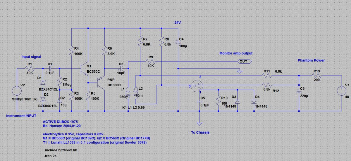
-
AuthorPosts
- You must be logged in to reply to this topic.