Description
An IDeal PID Controller using OpAmp has been simulated in PSpice and the controller has been tested with a separately excited DC motor to check it’s tuning algorithm.
- Free
- Intermediate
- 11-20
- PSpice
- 9.2
- No
-
Introduction
PID (proportional Integral Derivative) control is one of the earlier control strategies. Its early implementation was in pneumatic devices, followed by vacuum and solid state analog electronics, before arriving at today’s digital implementation of microprocessors. It has a simple control structure which was understood by plant operators and which they found relatively easy to tune. Since many control systems using PID control have proved satisfactory, it still has a wide range of applications in industrial control. According to a survey for process control systems conducted in 1989, more than 90 of the control loops were of the PID type. PID control has been an active research topic for many years. Since many process plants controlled by PID controllers have similar dynamics it has been found possible to set satisfactory controller parameters from less plant information than a complete mathematical model. These techniques came about because of the desire to adjust controller parameters in situ with a minimum of effort, and also because of the possible difficulty and poor cost benefit of obtaining mathematical models.
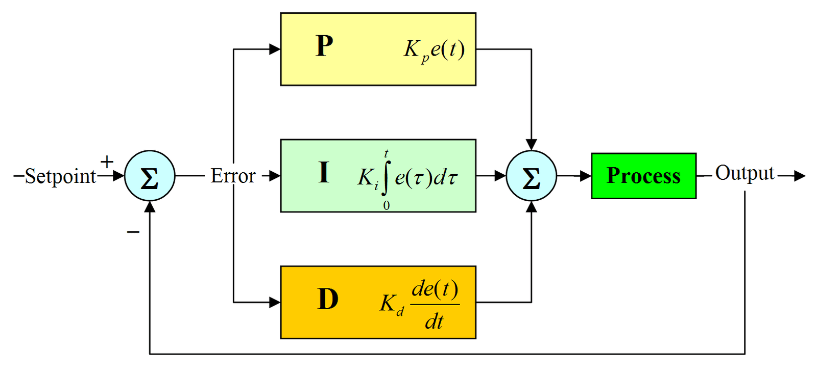
Figure. 1 Basic PID Controller Block diagram for controlling DC Motor
The goal in this chapter is to design a PID controller with the tuned gains of Chapter 8 with active circuits. This can also be termed as ‘Physical Realization’ of the controller.
Different methods of Physical Realization
There are many methods of physically realizing a controller or compensator. Two general way of implementing controllers are:
Analog Implementation
Digital ImplementationAnalog implementation is preferred over digital implementation when the system considered is not necessarily to be very fast in response such as responsive of μsec limit. Also digital implementation needs complex circuitry which is costly. That’s why analog implementation has been preferred in this thesis work. Analog implementation can be done in 3 ways:
Parallel PID Algorithm
Series PID Algorithm
Ideal PID AlgorithmParallel PID Algorithm
This method is very robust and easily tunable. Using variable capacitors and resistors, it can be easily tuned. It can be implemented as follows:
Figure 2 Parallel PID Algorithm
Series PID Algorithm
This implementation is also popular. It uses a PI controller and a PD controller in cascade.
Figure 3 Series PID Algorithm
Ideal PID Algorithm
In Ideal PID Algorithm, a simple inverting amplifier is used to implement PID controller. It’s response and tenability is slower than the other two algorithm but because of cost effectiveness, 3rd method has been chosen for the thesis work.
Figure 4 Ideal PID Implementation
The transfer function of the inverting amplifier is:
T=-Z_2/Z_1
With proper choice of Z2 & Z1, it can be shown that:
Above equation corresponds to a PID controller.
Physical Realization of the Controller
The classical implementation of PID controller or the active circuit realization of the controllers contains several active elements to realize the transfer function. For instance, parallel structures using Operational Amplifiers (Op-Amp) requires 5 amplifiers: Differentiator, P, I, D Op-amp and adder. At least 3 operational amplifiers are needed to implement a PID controller:
Integral - Need one Op-amp to perform integration of input signal.
Derivative - Need one Op-amp to perform derivative of input signal.
Proportional - Need one Op-amp to provide proportional gain.Utilizing Operational amplifier, all the conventional industrial controller as well as compensators can be realized.
Figure 5 Typical Inverting amplifier
The transfer function of an inverting amplifier whose configuration is repeated in Figure 9.2 is:
(V_0 (s))/(V_i (s) )=-(Z_2 (s))/(Z_1 (s) )
By judicious choice of Z1(s) and Z2(s), the circuit of Figure 9.5 can be used as a building block to implement PID controller. The block diagram of PID controller is as follows:
Figure 6 PID block diagram
From the block diagram, the transfer function of the PID controller is found as:
By putting the desired gains, a function of S will be formed. From there, the equation will be compared with the active realization of Figure 4. Three equations with 4 unknown parameters will be formed. After that, value of one parameter will be selected arbitrarily corresponding to near practical value, than other parameters will be calculated from the equations.
Figure 7 Active realization of controllers using operational amplifier
If gain of PID controllers if taken as follows:
K_p=10,K_d=1,K_i=8
Than the transfer function of the PID controllers will be as follows:
GC(s)=(K_d s^2+K_p s+K_i)/s = s+10+8/s (1)
Comparing the PID controller of Figure 4 with Equation 1, the following three relationships were obtained:
Proportional Gain, Kp = R_2/R_1 +C_1/C_2
.
Integral Gain, Ki = 1/(R_1 C_2 )
.
Derivative Gain, Kd = R2C1R_2/R_1 +C_1/C_2 =10 (2)
R2C1=1 (3)
1/(R_1 C_2 )=8 (4)
Since there are 4 unknowns and 3 equations, practical value of any one parameter is chosen arbitrarily.
If C2 = 0.3 μF than remaining values are found:
From Equation 9.4: R1 = 416.67 KΩ
From Equation 9.3: R2 = 365.4 KΩ
From Equation 9.2: C1 = 2.74 μF .
Using these values, the complete circuit is simulated in PSPICE.PSPICE Schematics
Cadence® Pspice® is a circuit analysis program, developed by MicroSim Corporation, based on the well known SPICE program (Simulation Program for Integrated Circuit Evaluation) developed at the University of California-Berkeley. The name is an acronym for Personal Simulation Program with Integrated Circuit Emphasis.
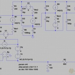
Figure 8 PSPICE Schematics of PID controller using Op-amp
Using PSPICE, PID implementation has been done by operational amplifier. Figure 8 is a PSPICE schematics drawing of active circuit realization of PID controller using operational amplifier.
Summary
In this project, a novel approach has been taken to physically realize the PID controller using ‘Ideal PID Algorithm” which uses operational amplifier as a building block to design controllers. In spite of unknown feedback voltage at the input of the PID controller, schematics have been drawn based on the values of the active circuits (Resistance, Capacitance) calculated by the Ideal PID Algorithm method. With the value of the feedback voltage known, a transient analysis can be done.


Reviews
There are no reviews yet.