Description
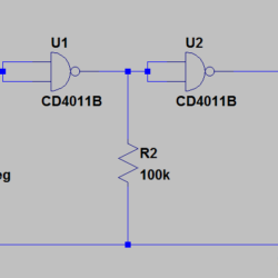
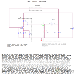
A PWM circuit is a good solution to control the amount of power to a load, acting on the duty cycle on-off of the switching. In this project a 7414N Schmitt input inverter is connected as simple oscillator. The frequency oscillation is about 1/(6.28*R*C). This oscillator feeds the clock of a 4 bit counter 74HC163.The outputs counter generates the sequence 0000 to 1111 continuously with voltage from 0V to 5V, that feed a weighted summer amplifier implemented with the first LM324 operational amplifier.its output is a negative value increasing in absolute value. The second LM324 multiplies the value by -1/2 generating a triangle positive waveform.This output with a DC level signal are the inputs of a comparator to generate the PWM signal.


Reviews
There are no reviews yet.