In the previously discussed article titled “ARDUINO Simulation PCB and 3D Models Libraries for Proteus,” we delved into the process of incorporating ARDUINO simulation components, footprints, and 3D model libraries into Proteus. In continuation of this, our focus now shifts towards understanding the straightforward utilization of these component models to simulate ARDUINO projects effectively. As an illustrative example, we can consider the simulation of a LED control project that has been implemented with a microcontroller. This walkthrough will illuminate how these libraries facilitate seamless project simulation, contributing to an enhanced development and testing workflow.
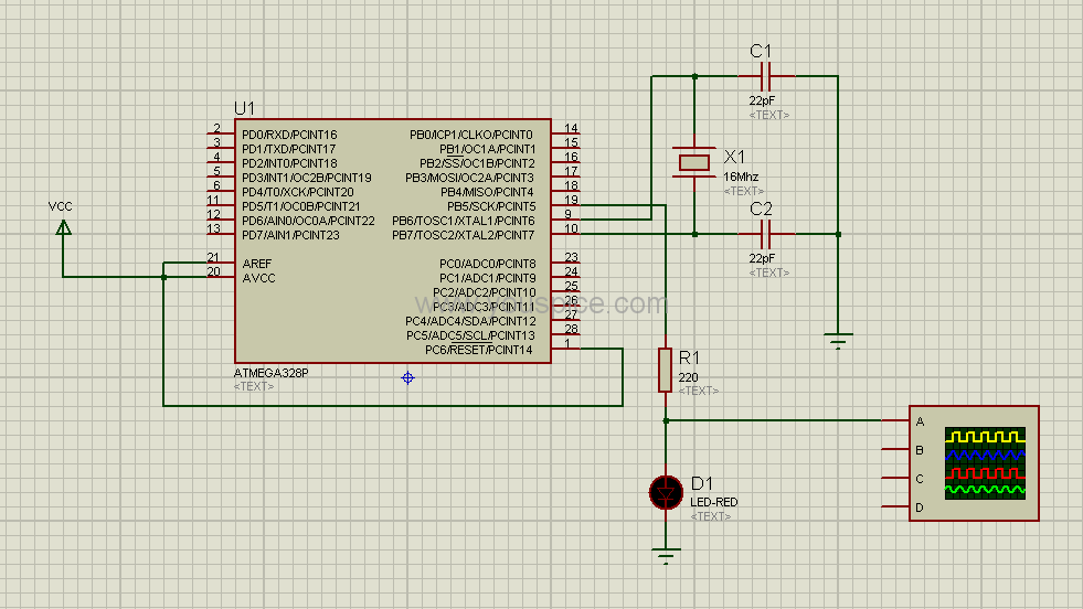
Fig. 1 Simple project implemented with a microcontroller model
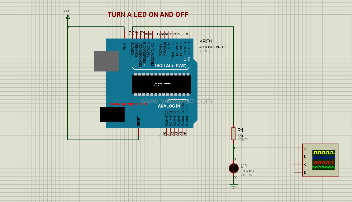
The ARDUINO UNO simulation model offers us the possibility to substitute the microcontroller, capacitors, and crystal oscillator components. This substitution allows for a comprehensive virtual representation of these elements within the simulation environment.
Fig. 2 The same project above implemented with ARDUINO UNO simulation model
It’s important to highlight that there’s a distinct numbering for the PB5 output in the two models. Despite this differentiation, it’s worth noting that the .hex file remains compatible with both models, as well as with the project that has been executed using the ARDUINO Pro Mini model.
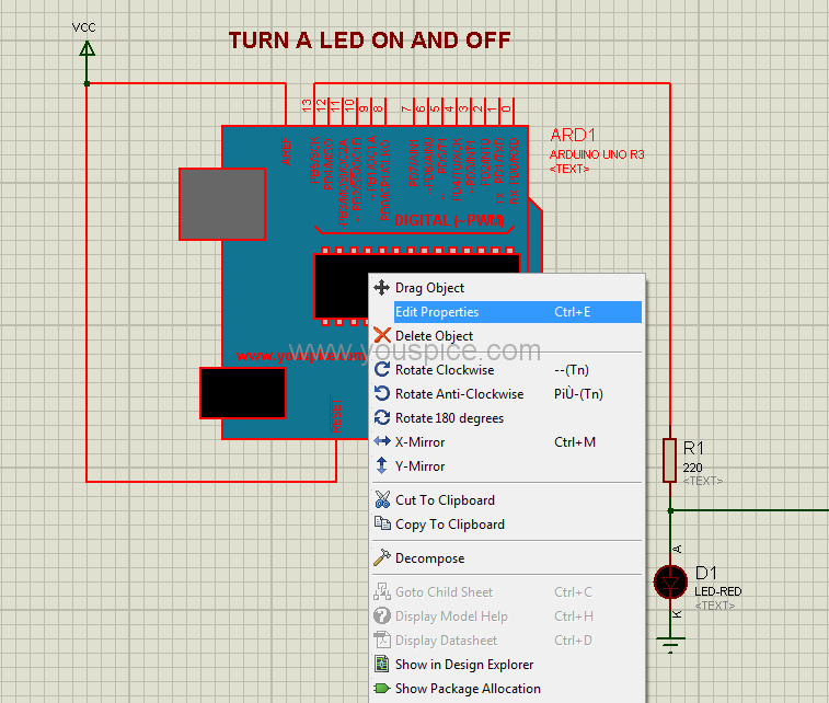
Right-click on the model and select the option “Edit Properties” from the context menu:
Fig. 3 Edit Properties
Upload the hex file of the blink project by selecting the “Program File” edit field and loading the respective hex file:
Fig. 4 Load the Hex file
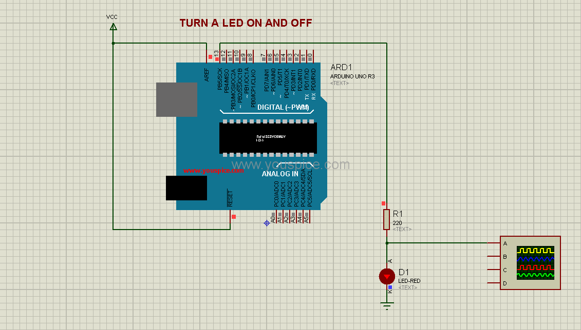
To conclude, let’s initiate the simulation by running the process:
Fig. 5 Run th simulation


