Video tutorial EDWinXP

EDWinXP Video tutorials

Welcome to our dedicated page showcasing a carefully curated collection of EDWinXP video tutorials available on YouTube. Our aim is to provide a valuable educational resource for individuals seeking to enhance their proficiency with EDWinXP, a versatile software platform for circuit design and analysis.

Within our collection of EDWinXP video tutorials, you will find a structured approach to mastering various aspects of the software. Whether you are a novice or an experienced user looking to deepen your expertise, our tutorials offer practical insights and guidance.

Our tutorials commence by acquainting you with the EDWinXP interface and its configuration options. This foundational knowledge ensures a smooth start for users as they embark on their journey of creating schematics and diagrams.

A prominent segment of our tutorial series is dedicated to the intricate process of VHDL to diagram conversion. We systematically demystify this process, enabling you to seamlessly translate VHDL designs into visual diagrams within the EDWinXP environment.

For those engaged in digital circuit design, our tutorials delve into the transition from truth tables to diagrams. These tutorials elucidate how to effectively represent logical functions graphically, thereby enhancing circuit design proficiency.

Furthermore, our tutorial series explores advanced topics such as DC, AC, and operating point analyses. These tutorials empower users with the ability to analyze circuit behavior under various conditions, a fundamental skill in engineering and design.

The comprehension of concepts related to poles and zeros is essential, particularly in control systems engineering. Our tutorials provide an in-depth examination of these concepts, equipping you with the knowledge required for effective control system design and analysis.

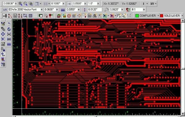
In addition to circuit design and analysis, our EDWinXP video tutorials comprehensively cover the domain of PCB design. You will find practical demonstrations on creating, editing, and optimizing printed circuit boards, simplifying the process of transforming schematics into functional PCB layouts.

Whether your endeavors involve academic projects, professional pursuits, or personal interests, our EDWinXP video tutorials serve as an invaluable resource, empowering you to maximize your utilization of this potent software tool.

Whether you are just embarking on your journey with EDWinXP or are a seasoned user looking to broaden your skill set, our video tutorials are a dependable companion. Join us in this educational endeavor as we unlock the potential of EDWinXP, making complex tasks accessible and pragmatic.

For a quick grasp of how to take your first steps with EDWinXP, read this article.


8051 Microcontroller Course- Embedded C and Assembly Language

TopicVideo
Creating Page Notes, Design Notes and Printing of Schematic
Filters Design
Initial Schematic Setting
TruthTable to Diagram Generator
VHDL to Diagram Converter
AC Transfer Analysis
DC Transfer Function Analysis
Operating point Analysis
Pole Zero Analysis
Small Signal AC Analysis
Transfer Function Analysis
Transient Analysis
Copper Pour creation and Copper Pour flood test
PCB Traces Clearence Check
PCB Traces Connectivity Check
Electromagnetic Analyzer
Thermal Analyzer
Signal Integrity Analyzer

The Art of Doing: Electronics for Everyone
Start designing, building, and playing with your own circuits today!!

EDWinXP SPICE Simulation

EDWinXP SPICE Simulation

EDWinXP SPICE simulation caters to a wide range of engineering needs. This versatile toolset comprises several essential components to facilitate the entire electronic project development process.

Schematic Editor The Schematic Editor serves as the frontend for project design, allowing users to create electrical schematics. Components are easily added to the logical diagram using the “Library Browser” or “Library Explorer” functions. Project validation is carried out using circuit simulators like the “Mixed Mode Simulator” and “EDSpice.”

Layout Editor With EDWinXP, project development can start from either the schematic or layout. Users can seamlessly transition between the two using “front annotation” and “back annotation.” The software offers two board-level simulators, “Thermal Analysis” and “Electromagnetic Analysis,” ensuring thorough scrutiny. Additionally, features like the “Signal Integrity Analyzer” help detect high-frequency signal distortions within traces, while the “Field Analyzer” is a graphical tool for studying electromagnetic fields generated by board activation or signal propagation on traces. The Layout Editor also incorporates a 3D concept for visualizing the designed board.

Fabrication Manager This module provides support for various PCB production phases. It enables users to create ground plans, add dimensions and notes, print layout drawings, extract NC data for drilling, and store it digitally or in hard copy. It also facilitates modification, sizing, and printing of drill shapes, PCB modification, Gerber and ASCII file generation, generic machine pick and place file creation, and material list generation.

Library Manager The Library Browser helps users navigate component lists (Parts, Symbols, Packages, Footprints) within available libraries. Various parts can be added to schematics or layouts through drag-and-drop or right-click actions. The Library Explorer lists available libraries, while the Library Editor allows users to add new components or modify existing ones. The incorporation of the 3-Dimension concept in the Library Editor facilitates package and cabinet adjustments, offering multiple perspectives and angles for visualization.

Other Features

  • Conversion Manager: Facilitates library and database format conversions, as well as the import and export of wirelists, schematics, and layouts in various formats.
  • Waveform Viewer: Used to represent simulation results in diagram form for Mix Mode, EDSpice, and Signal Integrity simulations.
  • Subcircuit Adapter: Converts SPICE subcircuits into EDSpice format.
  • Model Parameters Editor: Simplifies the management and creation of model libraries.
  • List Generator: Generates component library and project details lists.
  • Netlist Import and Export: Streamlines the transfer of circuit connection information to and from other software supporting formats like Jedec, Cupl, Xilinx, Altera, and more.
  • Spice Netlist Import: Allows the import of circuit (.cir) and subcircuit (.sbc) files into the system, generating electrical schematics and preserving model parameters for various analyses.
  • Schematic DXF Export: Permits the export of EDWinXP schematics to AutoCAD DXF format.
  • Layout DXF Export: Performs a similar function for layout graphics.
  • VHDL Editor: Introduces VHDL support for describing digital system behavior.
  • Simulation Model Generator: Converts VHDL source files into simulation models.

EDWinXP thus offers a robust and comprehensive suite of tools to facilitate electronic design, simulation, and project management with precision and efficiency.

To delve deeper into the various features and gain confidence  with EDWinXP SPICE simulation, consult this article of video tutorials.


In this article, we’ll study a Series Voltage Regulator schematic circuit using the SPICE simulation software EDWinXP. After the installation, run the program:


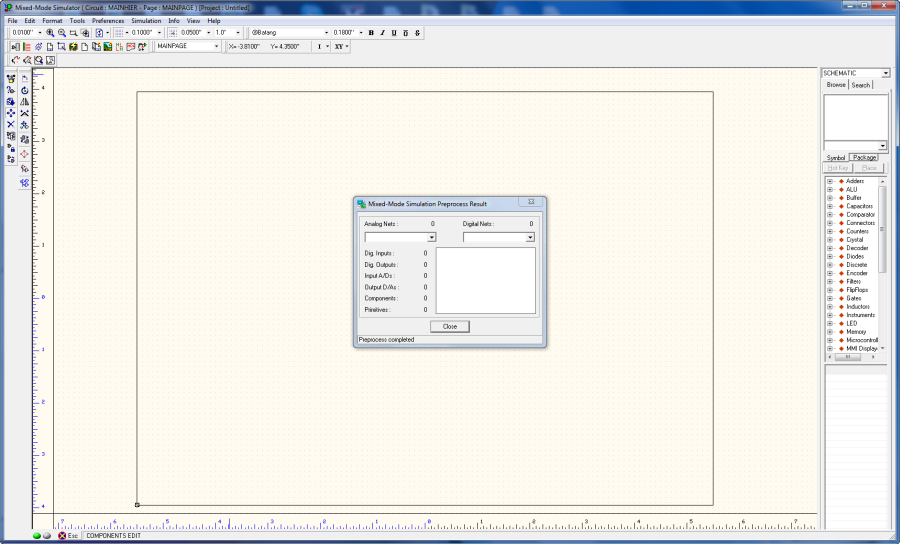
Let’s create a new project by selecting ‘Edit Page’ from the MAINPAGE.


It opens a new page


mainpage