Proteus can performs a mixed-mode SPICE circuit simulation of analog devices with a variety of models of microprocessors for a complete microcontroller based design. This feature is called VSM Virtual System Modelling. It can performs RS232 dynamic simulation, I2C simulation and debugging , SPI simulation and debugging, USB simulation, keypad and LCD system simulation functions, it also has available various virtual instrument devices , such as oscilloscopes, logic analyzers, signal generators. Proteus Also supports third-party software to compile and debug environment, such as Keil uVision IDE software. Keil uVision is an integrated development environment that combines project management, code editing, program debugging and other facilities in a single environment.
In the context of Proteus with Keil, here’s a straightforward example illustrating a debugging session of a Proteus simulation project with Keil. Communication is established via TCP/IP. The key advantage of this method is that a debug session can be conducted on either a single computer or two computers connected through the local network, all without the need for any external hardware.
The heart of the circuit features an AT89C51 microcontroller. A seven-segment 6-digit LED display is interfaced with the microcontroller. The segment code pins (a, b, c, d, e, f, g, dp) are linked to microcontroller port P1, while six pins of port P2 are connected to the digit code pins (1, 2, 3, 4, 5, 6). The objective is to display LED characters with a strobe effect.
In case you’ve never worked with Proteus, this article provides a guide to get started.
this is the schematic of the AT89C51 microcontroller connected to the 6-digit LED display
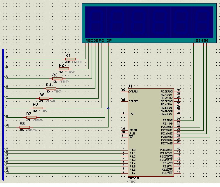
Let’s create the circuit schematic:

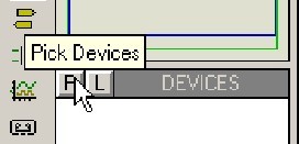
Add the necessary components to the object selection window. Select the components for the schematic by clicking the Object Selector button, as depicted in the image below:
In the ‘Pick Devices’ window, modify the ‘Keywords’ input to ‘AT89C51’ to search for the object library, and the search results will be displayed as illustrated:
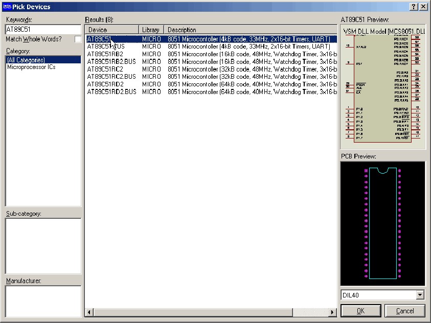
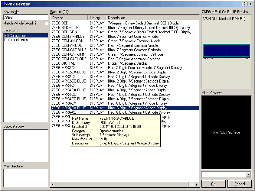
“In the ‘Results’ column, choose the first item, ‘AT89C51’. Then, in the ‘Pick Devices’ window, modify the ‘Keywords’ to ‘7 SEG’ and select ‘7SEG- MPX 6 – CA – BLUE’ (6-digit common anode 7-segment LED display), as demonstrated in the image:
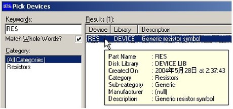
Lastly, modify the ‘Keyword’ to ‘RES’ and choose the single result, as indicated:
Click the “OK” button add the component to the devices window.

