
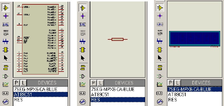
After performing the previous operations, the object selection window now contains three component objects: a ‘7 SEG – MPX 6 – CA – BLUE,’ ‘AT89C51,’ and ‘RES.’ If you click on ‘AT89C51,’ in the preview window, you can view the physical device. Similarly, when you click on ‘RES’ or ‘7 SEG – MPX 6 – CA – BLUE,’ in the preview window, you will see the RES and 7 SEG – MPX 6 – CA – BLUE devices, as shown in this image:
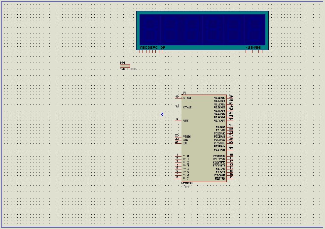
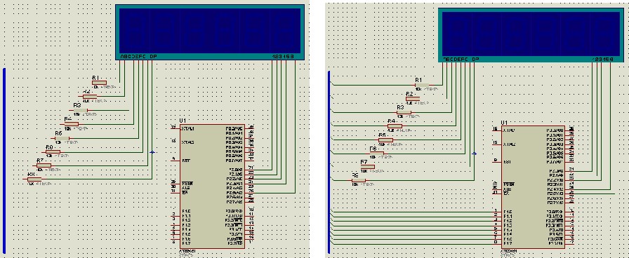
At this point, you’ll notice that the Component Mode button in the drawing toolbar is selected. Place the components as shown in the schematic below
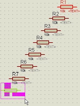
“Since the resistance values for R1 – R8 are the same, you can duplicate them using the copy function. Hover your mouse over R1, right-click, select R1, click the Copy button in the standard toolbar, drag the mouse, press the left mouse button to copy the object to a new location, and continue this process until you are finished. To end the copying, right-click.
Now, let’s add the bus to the graphics editor window. Click the Drawing button on the toolbar for the bus to select it. Hover the mouse over the graphics editor window, click the left mouse button to set the starting position of the bus, then move the mouse. You will see a thin pink line on the screen. Position the end of the bus where you want it, click the left mouse button again, and then click the right mouse button to confirm and complete the drawing of the bus. Afterward, the thin pink line will be replaced by thick blue lines, as shown
Wiring Up Components on the Schematic.
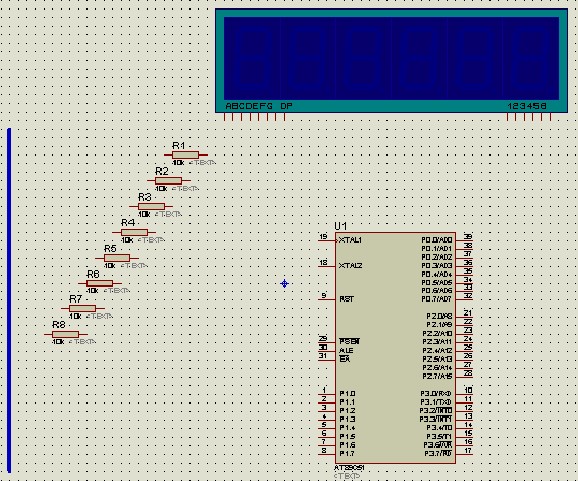
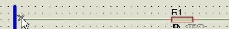
Proteus can automatically detect when you want to draw a connection line. Below, we will connect the right end of resistor R1 to the A-side LED of the display. When the mouse pointer is near the right end of R1’s connection point, a ‘×’ symbol will appear, indicating that it has found the connection point of R1. Proteus features an automatic path function for lines (referred to as WAR). After selecting the two connection points, WAR will choose an appropriate path for the connection. We have already learned how to enable this feature in a previous lesson. You can similarly complete other connections. At any point during this process, you can press the ESC key or right-click to stop drawing lines
Label the wire bus connections: PART LABELS.
Click on the Drawing toolbar’s Wire Labels button to select it. Position the mouse pointer over the wires you want to label, and you will see a ‘×’ symbol on the mouse pointer, as shown:
Click the left mouse button to open the Edit Wire Label window, as depicted. In the ‘String’ field, enter the label name (e.g., ‘a’), and then click the ‘OK’ button. Likewise, you can label other leads as shown. Please note that during the labeling process of conductor pins, each of the conductors must be marked with the same label name.
