TINA Video Tutorials

TINA Video tutorials

Welcome to the dedicated TINA Video Tutorials page, a valuable resource of educational content aimed at helping you master the intricacies of TINA software. In today’s fast-paced technological landscape, the ability to design, analyze, and simulate electronic circuits efficiently is paramount, and TINA Design Suite stands as a powerful tool to meet these challenges. Here, we delve into the world of TINA Video Tutorials, designed to cater to individuals at all levels of expertise.

For those just starting their journey into circuit simulation, these Video Tutorials provide a solid foundation. Beginners can explore fundamental aspects of the simulation environment, gaining insights into creating and analyzing electronic circuits. These tutorials serve as a gentle introduction, gradually acquainting you with TINA’s user-friendly interface and its wide array of features.

Other TINA Video tutorials delve deeper into the intricacies of TINA, such as comparing simulations to real-world measurements. By studying AC analysis and Fourier analysis, you’ll be equipped with the skills to analyze circuit behavior under different conditions. You’ll also learn how to create subcircuits from schematics, enabling modular circuit design and reuse.

For advanced users, TINA Video Tutorials offer a deep dive into the software’s advanced capabilities. You can explore topics like interactive logic gate testing, VHDL circuit design, and PCB development. These advanced features empower you to tackle complex circuit design challenges with confidence, precision, and efficiency.

These selected video tutorials provide step-by-step guidance, ensuring that you not only understand the concepts but also gain practical experience. The goal is to equip you with the tools and insights needed to unlock TINA’s full potential, enabling you to design and analyze circuits with precision and ease.

8051 Microcontroller Course- Embedded C and Assembly Language

TopicVideo
Introduction to TINA Design Suite
Comparison of simulation and real time measurements
Real time transient recording and comparison with simulation
RC transient and AC analysys
Fourier analysis
Active band pass filter
How to make subcircuits from schematics
Test a logic gate in interactive mode
Bus example
Pic flasher circuit
VHDL circuits
Create a simple PCB
Importing SPICE Models into TINA

The Art of Doing: Electronics for Everyone
Start designing, building, and playing with your own circuits today!!

Importing SUBCKT PSpice Netlist into TINA

Importing SUBCKT PSpice Netlist into TINA

This article aims to offer a thorough exploration of Importing SUBCKT PSpice Netlist into TINA, focusing specifically on their application through the SUBCKT subcircuit statement. While the foundational syntax for basic components like resistors, capacitors, and inductors remains consistent across both TINA and PSpice platforms, the complexity increases when working with more elaborate models. In the case of more intricate models, it’s possible that certain PSpice netlists could encompass formats that are incompatible with TINA.

The article addresses this challenge by offering a detailed, step-by-step guide on importing a PSpice netlist into TINA. The primary objective is to ensure seamless syntax compatibility, ultimately resulting in the creation of a TINA macromodel.

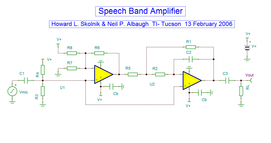
To provide practical insight, we will employ the schematic of a speech band amplifier from TINA Designsoft’s extensive circuit collection. Within this circuit, we will showcase the application of two opa345 operational amplifiers, offering a tangible and illustrative example for our exploration into the process of Importing SUBCKT PSpice Netlist into TINA.

In addition, another article that might interest you for importing PSPice models into TINA is this one


Speechbandamplifier


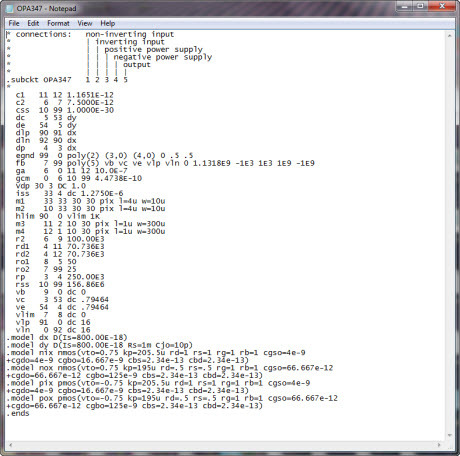
We want to replace the SPICE model of the opa345 with the following opa347 PSpice netlist, which includes the SUBCKT statement:


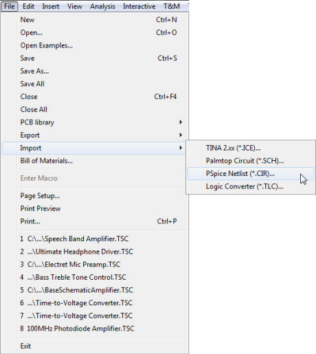
rename the .txt file as opa347.cir, then from the menu File, choose Import, PSpice Netlist (.CIR)


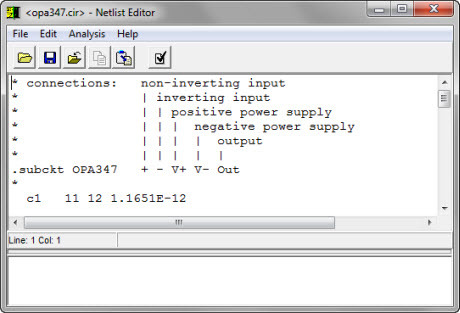
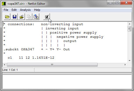
When you select the ‘opa347.cir’ file, the Netlist Editor window opens


Click on the ‘Compile’ icon to verify the compatibility of SPICE statements with TINA. If there are no compatibility issues, a ‘Successfully completed’ message appears:


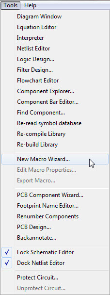
Close the Netlist Editor window, and then select ‘New Macro Wizard…’ from the ‘Tools’ menu


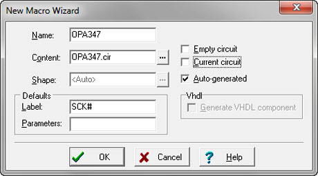
The “New Macro Wizard” window will appear. Enter “opa347” as the name and uncheck the “Current circuit” option. Now, you can select the file “opa347.cir” using the directory window. Make sure to uncheck “Auto-generated.”


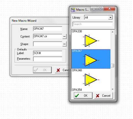
Click on the “Shape” ellipsis icon and choose a graphic symbol from the list. If there are no symbols that accurately represent our model, you can leave the check in the “Auto-generated” box:


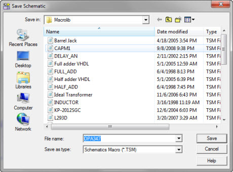
Save the macro (.TSM file) for example in the Macrolib directory:


TINA spice simulation

TINA SPICE Simulation

TINA is a versatile and user-friendly software tool that empowers users to design, simulate, and optimize electronic circuits with precision and efficiency. Its extensive feature set and TINA SPICE simulation capabilities make it a valuable resource in the field of electronics design and analysis. Here are some key characteristics of TINA:

  1. Intuitive User Interface: TINA boasts an intuitive and user-friendly interface, making it accessible to both beginners and experienced users. Its drag-and-drop functionality and interactive components simplify the process of designing and simulating circuits.
  2. Extensive Component Library: TINA provides an extensive library of electronic components, including semiconductors, passive components, and specialized devices. This library allows users to quickly build complex circuits by selecting and configuring components.
  3. SPICE Simulation Engine: TINA is powered by a robust SPICE (Simulation Program with Integrated Circuit Emphasis) simulation engine. This engine accurately models the behavior of electronic components and circuits, enabling users to predict how their designs will perform in the real world.
  4. Mixed-Signal Simulation: TINA supports mixed-signal simulation, allowing users to design and analyze circuits that combine analog and digital components. This is particularly useful for designing integrated systems.
  5. Parameter Sweeps and Optimization: Users can perform parameter sweeps and optimization studies to explore different design scenarios and find the optimal values for circuit parameters. This feature helps in fine-tuning designs for specific requirements.
  6. Interactive Waveform Analysis: TINA offers advanced waveform analysis tools that allow users to examine voltage and current waveforms at various points in the circuit. This helps in identifying and troubleshooting issues in the design.
  7. Interactive 3D PCB Design: TINA includes a 3D PCB design module that enables users to create and visualize printed circuit boards. This integration streamlines the transition from schematic design to PCB layout.
  8. Educational Resources: TINA is often used in educational settings due to its educational versions and resources. It provides a practical platform for learning electronics and circuit design principles.
  9. Integration with Microcontrollers: TINA can interface with various microcontrollers, making it suitable for embedded systems design. Users can simulate the interaction between microcontrollers and external circuitry.
  10. Custom Component Creation: For unique or specialized components, TINA allows users to create custom models, ensuring accurate simulation results for specific components or devices.

In this initial undertaking, we will commence our initial endeavors with TINA SPICE Simulation by formulating a three-stage BJT audio amplifier circuit. This preliminary endeavor aims to demonstrate the functionality of TINA while concurrently establishing a substantial groundwork for comprehending the complexities associated with electronic circuit design and simulation. Thus, we shall proceed to investigate the captivating domain of electronic design with TINA SPICE Simulation.

To delve deeper into the software’s features, you can refer to this article.


After running the program, we can see this window:


Globalview


On the components toolbar, there are devices in the ‘basic’ tab. Below the toolbar, when you select ‘semiconductors’ on the toolbar, several types of semiconductors appear:


Now select “Special”


And once again, we have a large number of devices to choose from. Let’s begin by selecting a resistor:


Place Resistors, to set value, double-click on one, and a parameters window will appear