Forum Replies Created
-
AuthorPosts
-
September 18, 2013 at 8:35 am in reply to: How do you open a .TSC file extension in mulitsim 11 #16448
Hi,
the .tsc is a TINA schematic file that you can open with TINA or TINA-TI. If you want open a schematic file of another platform with Multisim, you have to import the netlist of the circuit. In the nimultisim videotutorials page you find the video “Import a SPICE list” where the two methods to import a netlist in Multisim are well explained: the SPICE block method where you can paste in the text of the netlist to be simulated and the Netlist importer method.
Hi Amcfarl,
my opinion is that the architecture of the CPU can not give you great advantages compared to more powerful processors .Below you can find the link to a detailed CPU Benchmarks. It’s not a specific SPICE benchmark but you can get good information from this list. The AMD Opteron 6272 ranks 19th and has a good price, even though the best perfomance/price ratio is the Intel Core i7-3930K 3.20GHz. Of course it is very important the RAM speed.
Hi again David,
I’ve attached an updated spice model of Bo Hansen DI-box. The picture you’ve linked in the first post
refers to an old schematic, some components have been changed.
R3 and R4 are now 100K, and C2 10 uF.R10 changed to 100 ohms and C5 0.1 uF.In the previous file
I ‘ve not reported correctly the fictitious voltage (provided by the phantom power): is not 48V but 24V.In this project file I’ve added the phantom power supply. About the Lundhal LL 1538 transformer, the L1/L2 ratio is ok, but I’ve changed the values of the impedances to values more suitable for the size of the transformer.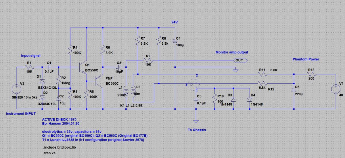
in the previous schematic the Q2 transistor has to be mirrored.
Both ends of the transformer windings have to be at the same DC potential, and L2 should be closed
to the impedance that must be adapted, I don’t know exactly in your case.
you can see more details in the pdf attached.Hi David,
it seems a very good project. In your schematic there are several mismatches respect to the original project.The transistor Q2 is a PNP, not a NPN, I’ve uploaded the transistors library bjtdibox.lib to add in
..LTCLTspiceIVlibsub directory. Inside there are spice models of BC550C and the PNP BC560C.
I’ve added a directive to include the library in the new .asc file.The DI-box project use a 5:1 transformer,
this ratio normally refers to turns and then voltages ratio, not to inductances ratio, and in your schematic are reversed. If the turns ratio is 5:1 the inductances ratio must be 25:1, for example L1=250H and L2=10H.
Now you should be on the right track, let us know about your results and if you like share them with the community.cheers
Hi shapein,
varitone solution uses only passive filters with a fixed number of capacitors and then
it’s a discrete solution, I think because the difficulty to get a variable capacitance to the audio
frequencies or even because the capacitance changes without keeping the Q factor constant.
They are used in old radio receivers but are pretty bulky.
The solution that could fit for you is in the circuit I’ve attached below, with an active filter, which uses
an operational amplifier to emulate a variable inductance and then get the same result of shifting the
resonance frequency.I’ve tried with different fixed capacitors value
together with the variable inductance, 10nF, 2nF, and 470pF and I’ve found these results.At
low frequency there’s a quasi constant x-shift of filter response.
You can run the simulation with the 9.1 PSpice student version.I hope it can be useful.
greetingsVery good. vanilla2 is a must to boost contribution and collaboration.
-
AuthorPosts