Forum Replies Created
-
AuthorPosts
-
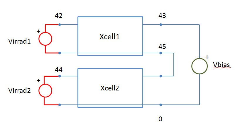
I’ve uploaded the images below If you have problems to figure out how the nodes of solar cells are enumerated
the three series solar cells and the the first cell_3.cir
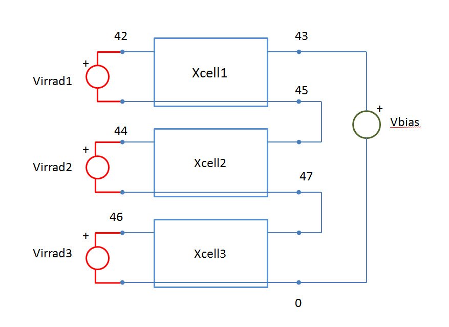
virrad2 and virrad3 are misplaced. The correct version is:
virrad2 44 47 dc 1000
virrad3 46 0 dc 1000Hi raheemq,
Virrad, in the SPICE model, is a voltage, but actually it represents numerically the value of the Irradiance.
The irradiance is measured in W/m^2 and considers the contributions of all wavelengths to the power that affects a surface.
As a first approximation, an ideal solar cell can be modelled in SPICE by a voltage controlled current source, that receives an Irradiance (represented by Virrad) and provides a short circuit current proportional to the irradiance, and a diode that represents the open circuit voltage. (subcircuit cell_1).
cell_3.cir refers to cell_2 subcircuit that is a generalized SPICE model of a solar cell that includes series and shunt resistance and two diodes that model other important electrical characteristics of the solar cell.
If you want add a third series solar cell you can do for example:xcell1 45 43 42
xcell2 47 45 44
xcell3 0 47 46
then you add virrad3 between 0 and 46.
Ciao Roberto,
add directive:
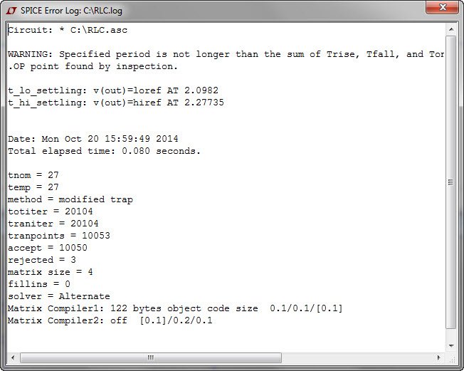
.MEAS TRAN settling_time PARAM max(t_lo_settling,t_hi_settling)
Hello rbacchi,
You were on the right track. I’ve applied the .MEAS directive to this simple second order RLC circuit:
I’ve chosen the components values ​​to make it quite underdamped:
go to “View” menu, and click SPICE Error Log file (or CTRL+L).
the higher value is the settling time. If you want a 2% settling time, simply set settling_percent=2.
Hi sumandebnath2014,
the document I’ve uploaded gives a detailed explanation of the induction motor’s SPICE model. I think it’s a very good starting point. I hope it will be useful. Let us know.
Bye
This is the simulation of your circuit with PSpice 9.2:
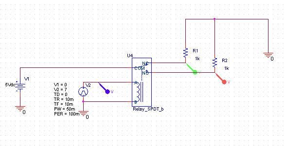

As you can see it works fine.
On 16.X versions the simulation give an error convergence problem. The simulation profiles are identical.
I noticed that sometimes there are convergence problems in the last versions not present in the older versions.I think that PSpice programmers have tried to make improvements in the algorithm convergence that in some cases give worse results.February 12, 2013 at 9:07 am in reply to: MC33063 Buck Regulator Simulation using Cadence Orcad Capture+pSpice #16389Hi,
models and schematic are OK. you only have to fix some parameters. Check Skip the initial transient bias point calculation (SKIPBP), then run 20ms with a maximum step size of 1 us. It will work fine.Below the simulation on 10 and 100 Ohm.
Read this document: (http://www.m-hikari.com/ces/ces2008/ces1-4-2008/mahmoudCES1-4-2008.pdf)
You find in it a proposed DVCC model and the aspect ratios for its transistors. About how to simulate the CMOS with PSpice, read the discussion CMOS in PSpice.regards
Hi hurhassan
working in PSpice with customizable CMOS model is simple. I use 16.3 version, but it’s the same for 16.5.
Create a new project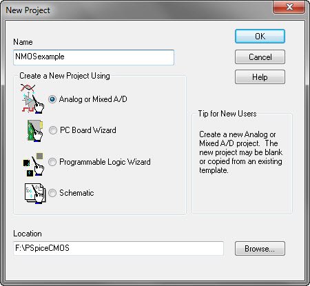
for a NMOS take MbreakN from BREAKOUT library and place on the layout
(for a PMOS take a MbreakP)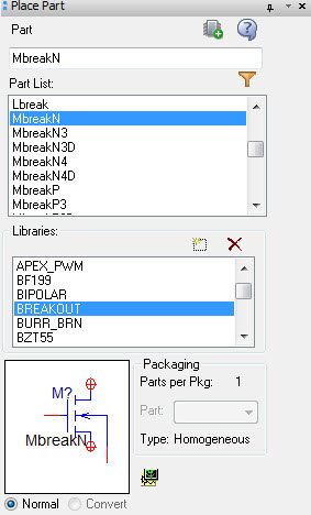
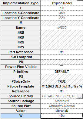
Select it, right click, “Edit PSpice model”, choose PSpice A/D, and then this window pops up
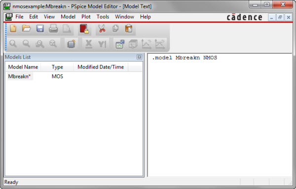
Excellent libraries for CMOS are available, for example you can use the cmosedu_models
by Jacob Baker. This a library for LTspice, Fortunately, the two syntaxes, with few exceptions, are compatible.To model a NMOS long channel, with 1 um minimum drawn channel length, copy the first .model statement and paste in the editor window, save
At this point right click on the CMOS, choose Edit Properties.Edit L 1u, and for example, W=10u
to perform a DC sweep analysis, draw this simple circuit
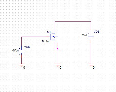
Add a netsted DC sweep simulation, and run
this is the PSpice simulation result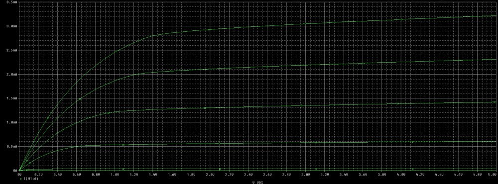
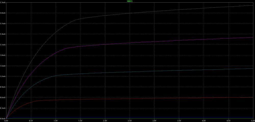
that obviously is the same of LTspice
Hi Mmilton,
I’ ve uploaded the model of a DC motor/Generator for PSpice. The model is simple.
You use the motor as a generator but the model is the same and the torque is supplied by the bicycle.
It could be interesting to study the dynamic conditions where the angular speed is not constant.No macro. There are three types of models in PSpice:
T, that is the easiest way to model a loseless transmission line,
you have to insert characteristic impedance Zo value and
the electrical lenght TD (for example if the signal velocity in a cable is V= 0.75*c, where
c is the speed of light, TD=20ns it means that 0.75*c*20ns= 4.5mtr ).
Often Zo is known, or for a coax cable you can find out as SQRT(L/C) where L and C are provided
by vendor or as Zo= 60/SQRT(εr) * ln(b/a) where εr is the dielectric constant, a is the diameter of the inner conductor and b is the diameter of the inside surface.
Tlossy models a lossy transmission line and a loseless line
with R=G=0. For a coax cable R is modeled as Rs/6.28 *(1/b+ 1/a), where Rs is the
skin effect resistivity [Ohm], the G parameter is 6.28* σ/(ln(b/a)), where σ is the conductivity [Siemens/m].
At last we have the Tlumped model.This is made by a finite numbers of sections of cable and can be used when
TR/TD >=4 in the single section.(TR is the rise time of the pulse). More are the sections and more accurate is the result.Hi Jtwain80,
For transmission lines has no sense speak of voltages and currents but rather it need speak about waves of voltage and waves of currents.
When you solve a circuit like an audio amplifier or an operational amplifier circuit, applying the kirchoff laws and other electrical laws, implicitly you are assuming that the circuit is working under the
condition of lumped circuits. What does this mean? it means that considering the work frequency, the relative wavelength is very large compared with circuit dimensions. So you can assume that the change of electric signal (voltage and current) propagates instantaneously along the circuit.
Actually when the frequency rises and the wavelength become comparable with the circuit dimension, this approximation is no longer valid, now we are in the domain of distributed circuits and transmission lines. A little piece of coax cable (actually infinitesimal) or microstrip behave
like a little capacitor and a little inductor, that we could write as C*dx e L*dx , where x is the longitudinal lenght of cable. Recalling the constitutive equations of capacitor and inductor easily we get probably the most famous equations for e.m.fields engineers after the Maxwell equations,
known as the telegrapher’s equations:
Combining these equations we get two wave equations.
The solution of this equations is the sum of a forward wave and a backward wave.
If a voltage pulse start from source a voltage pulse and then a current pulse travel along the transmission line, they can be partially or completely absorbed by a load, or partially or completely reflected, etc.
If the source start from the middle of a trasmission line, a wave travel long x and a wave long -x.
The constanto Zo = SQRT(L/C) [Ohm] is called the characteristic impedance of the transmission line an is the ratio of voltage to current for the traveling waves.L [H/m]and C[F/m] depend on the physical characteristics
of line.Hi Federico,
what type of transistor JFET or BJT? In any case, an hartley oscillator is not so easy to simulate accurately
because it uses several important concepts such as the resonance and the feedback.In the real circuit the
electrical noise is amplified by the tuned resonant circuit.
However, respecting certain rules of good design you can get excellent results.
For my experience if at the resonance frequency you use a resonant circuit with a
good Q factor, with an appropriate choice of inductance and capacitance, but above all, with a good biasing of the transistor, and this depends if you use a JFET or BJT, under certain conditions on the loop gain and gain of amplifier circuit imposed by the theory, you can get very good results.You can see here one of my projects. -
AuthorPosts