3.Circuit-breaker Model
The circuit-breaker model is shown in Figure 4. Current icb through the circuit-breaker flows between I/O pins cb+ and cb-, passing through the voltage source Vsense, voltage-controlled voltage source E(arc) and voltage-controlled switch cbmod1. Vsense acts as an ideal current meter.
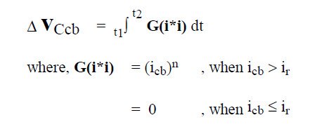
To model the thermal characteristic of the circuitbreaker, the current icb measured by Vsense is passed to the current-controlled current source G(i*i), which outputs a current equal to icb raised to the power n, whenever icb exceeds the rated current ir of the circuitbreaker. The change in voltage developed across Ccb is then,
By making the capacitor Ccb value equal to the prearcing i^ n *t of the circuit-breaker, in A^n *s, the voltage developed across Ccb at the end of the pre-arcing time is normalised to 1V. The thermal loss of the circuitbreaker is modelled by the resistor Rcb, which discharges the voltage across Ccb.
To model the magnetic characteristic of the circuitbreaker observed in Figures 2 and 3, a voltage source E(i), which is controlled by the current icb, outputs a voltage that linearly increases from 0 when the current level exceeds im1, rising to a maximum of 1V when the current level reaches im2. The diode D(i) and capacitor C(i) provide a peak hold function to allow the simulation to proceed in a latching action.
The arc voltage initially generated as the contacts break, Va, is modelled by a voltage sourced from E(arc). The voltage-controlled switch cbmod1 models the DC resistance of the circuit-breaker with closed contacts Rd, the resistance increase as the arc extinguishes, and the one-way action of the opening contacts. The input to E(arc) and cbmod1 is the voltage developed across both Ccb and C(i).
The switch cbmod1 is a digital subcircuit which switches off when its controlling input voltage exceeds 1V. The change in switch resistance during the off transition is controlled by a time delay factor Td and a resistance factor Rd. Three series connected resistance’s in cbmod1 model the circuit-breaker arc resistance increase.
Model parameter values are given in Table 1, based on typical measured characteristics of a 125A circuitbreaker.

a 125A circuit-breaker operating in 54VDC circuit with
5.2kA prospective current and 0.25ms prospective time
constant.


