Coupling and Decoupling networks.
Each coupling/decoupling network (CDN) consists of a decoupling network and a coupling element as shown below
For line-to-line coupling, the surge shall be coupled by an 18uF capacitor –Differential Mode:
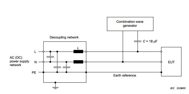
For line-to-ground coupling, the surge shall be coupled by an 9uF capacitor and a 10 ohm resistor –Common Mode:

The EUT device is The Equipment Under Test.
Examples of three phase line-to-earth and line-to-line CDNs
Surge Generator Validation.
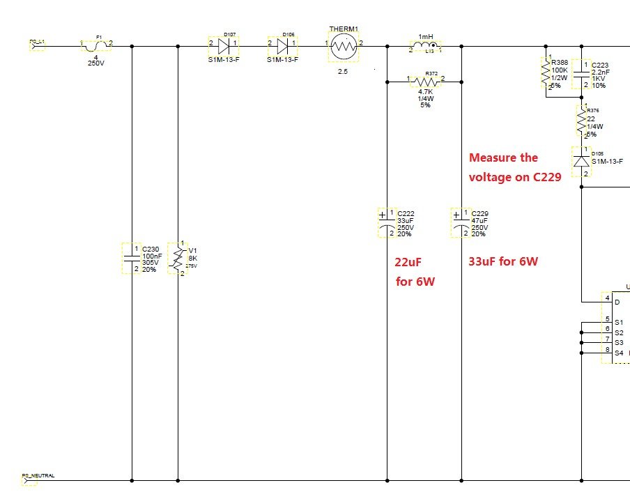
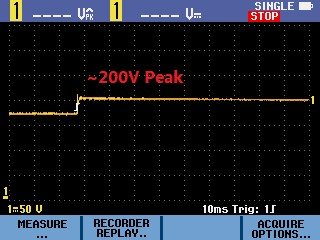
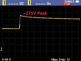
Sahara3 6W board was used to validate the surge generator by measuring the voltage on C229 and comparing with simulation results at 1KV surge and 3KV surge in standby mode, Standby power about 1W
below a 1KV Surge on Sahara3 6W board, 90 degree Voltage between the MOV varistor.
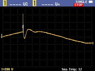
3KV Surge on Sahara3 6W board, 90 degree. Voltage between the MOV varistor:

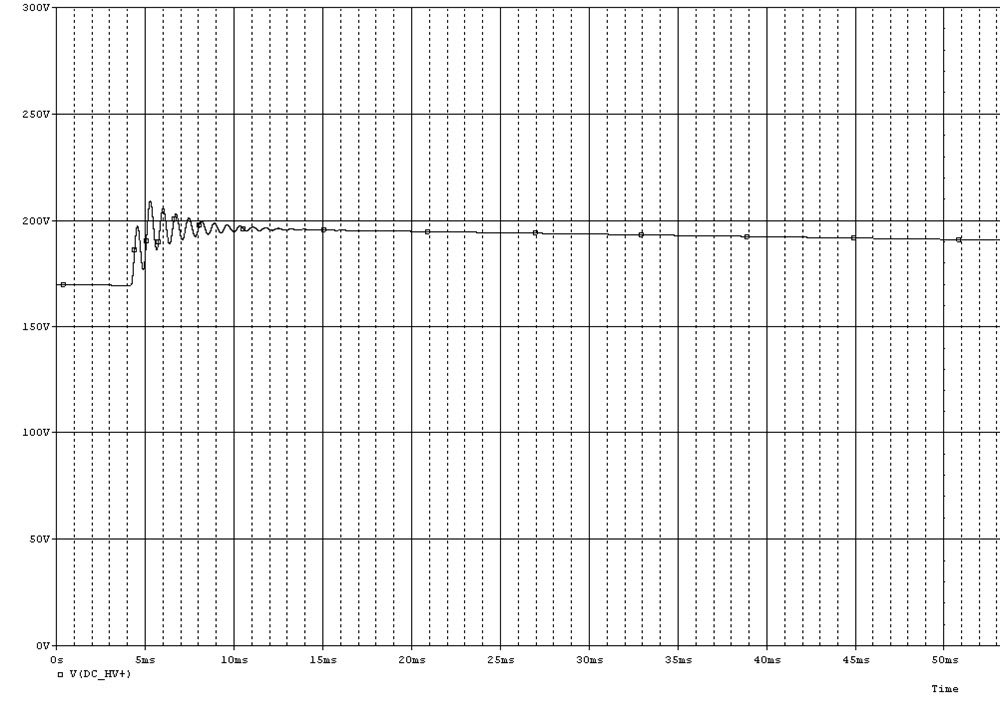
1KV Surge on Sahara3 6W board, 90 degree. Voltage between C229:
3KV Surge on Sahara3 6W board, 90 degree. Voltage between C229:
Thanks for this article to ssleandro.


