
According to the IEC 61000-4-2 standard, the current waveform has to be verified with a low ohmic current sensor. In fact, about the measurement of discharge current, the standard write: “coaxial current target used to measure the discharge current of ESD generators shall have an input impedance, measured between the inner electrode and ground, of no more than 2.1 Ohm at d.c.”. Thus, in order to measure the simulated discharge current, a 2-ohm resistor is used.

Figure 3 The ideal ESD waveform and the SPICE-simulated ESD at 4kV level
The SPICE simulated ESD waveform is shown in Figure 3 in blue; the red waveform is the ideal ESD waveform, as described in the specification’s formula. As can be seen, there is a good matching between the two waveform, in fact, the simulated currents at the first peak, 30ns and 60ns meet the IEC 61000-4-2 specification.
The Table 2 describe the waveform characteristics at different test levels (2 kV, 4kV, 6kV and 8kV) of the simulated generator versus ideal current waveform.
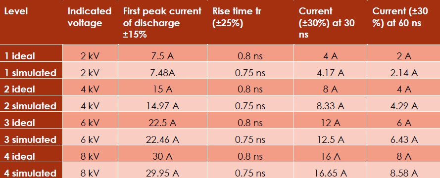
Table 2 The waveform characteristics at different test levels
THE LTSPICE MODEL
The circuit was build using LTSpice, a freeware SPICE simulator of electronic circuits but could be redesigned using other SPICE simulators.
The ESD-generator proposed is a parametric circuit, thus could be chosen:
-the IEC61000-4-2 test level (the ESD voltage) by setting the parameter “IEC61000_4_2_test_level” from 1 to 4 (see Table 2).
-the starting time of the ESD simulated phenomena by setting the parameter “td” with time in seconds.
The circuit shown in Figure 4 is the same as in Figure 2 with the addition of two voltage-controlled switch that implements the control on ESD starting time.
Control on ESD voltage is done setting the initial voltage condition of the two capacitor (see string “.ic V(c1)=4kV V(c2)=4kV”).
The circuit is saved on file: “IEC61000-4-2_ESD_Generator.asc”.

Figure 4 the ESD generator SPICE circuit
To simplify the use of the circuit, a symbol for this generator similar to ESD gun used in EMC laboratories is designed. It is available on file “IEC61000-4-2_ESD_Generator.asy”. To use the symbol, create a new folder and copy IEC61000-4-2_ESD_Generator.asy and IEC61000-4-2_ESD_Generator.asc files inside. Then, create a new LT-Spice schematic and add a new component selecting the top directory containing the schematic (see Figure 5). This folder will also contain the ESD generator symbol.
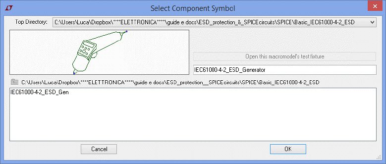
Figure 5 the select component symbol window
To set the parameters just right-click on the ESD-gun symbol and copy the string “IEC61000_4_2_test_level=<desired_level> td=<desired_time_delay>”on PARAMS text-box. Obviously change the <desired_level> and <desired_time_delay> with desired value as described in the schematic (see the blu text near the ESD-gun in Figure 6).
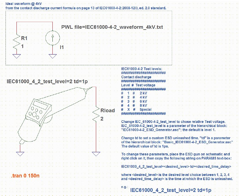
Figure 6 A schematic example
As visible in Figure 6, in “Example_IEC61000-4-2_ESD_circuit.asc”, there are the simulated ESD-generator and I1, a behavioral-current-generator. This current generator read the data from “IEC61000-4-2_waveform_4kV.txt” that is a PWL file containing data generated with Matlab© using IEC61000-4-2 ESD current formula.
Plotting I(R1) and I(Rload), it’s easy to compare the simulated current and the IEC61000-4-2 current (referred to level 2, 4kV ESD only) as shown in Figure 3.
RIGOL Digital Oscilloscope DHO924S 250MHz
BIBLIOGRAPHY
Pavlos K. Katsivelis, Georgios P. Fotis, Ioannis F. Gonos, Tryfon G. Koussiouris and Ioannis A. Stathopulos, “Electrostatic Discharge Current Linear Approach and Circuit Design Method,” Energies, vol. 3, no. 11, pp. 1728-1740, 2010.
IEC, International Electrotechnical Commission, Electromagnetic compatibility IEC 61000-4-2 (EMC) – Part 4-2: Testing and measurement techniques – Electrostatic discharge immunity test, 2008.
Texas Instruments Incorporated, “Electrostatic Discharge (ESD) Aplication Report SSYA010A,” June 2014. [Online]. Available: http://www.ti.com/lit/an/ssya010a/ssya010a.pdf. [Accessed 13 07 2014].
Fotis, G.P.; Gonos, I.F.; Iracleous, D.P.; Stathopulos, I.A., «Mathematical analysis and simulation for the electrostatic discharge (ESD) according tothe EN 61000-4-2,» in In Proceedings of the 39th International Universities Power Engineering Conference, Bristol, UK, 6–8 September 2004.
Prof. Dr.-Ing. Stephan Frei, Prof. Dr.-Ing. David Pommerenke, Dipl.-Ing. Bastian Arndt, «FAT/249-High-voltage coupling in electronic devices and control units,» [Online].