Control Systems using SPICE Simulation.

Ing. Cristoforo Baldoni

Exploring the domain of Control Systems using SPICE Simulation, this article offers essential principles for designing and analyzing Feedback and Control Systems. Control Systems theory, a cornerstone of engineering and automation, involves the study of dynamic systems and their manipulation to achieve desired outcomes. These systems are omnipresent in our modern industrial technological world, seamlessly integrated into everyday devices. They play a vital role in processes as diverse as the precise positioning of a Reader’s laser, the intricate control of a hard disk head’s movement, and even the numerous biological control systems orchestrating our bodily functions.

Control Systems theory involves understanding how systems respond to various inputs and disturbances, and how to design controllers that shape these responses to achieve desired goals. These goals can include stability, accuracy, speed, and overall performance optimization. Whether it’s managing the temperature of an oven, stabilizing the flight of an aircraft, or controlling the speed of a motor, the principles of Control Systems theory provide the framework to analyze, design, and optimize these dynamic processes.

As we navigate through this article, we’ll begin by introducing the basic concepts that underpin Control Systems theory. From there, we’ll seamlessly transition into exploring how these theories come to life through the application of SPICE simulation. Our journey includes the evaluation of the Open Loop Transfer Function using the versatile tool of PSPice, providing hands-on insights into the practical implementation of control strategies. Whether you’re a novice eager to comprehend the foundations or an enthusiast seeking to refine your expertise, this article offers a holistic perspective on the symbiotic relationship between Control Systems theory and the power of SPICE Simulation.

Topics Covered:

1.  Processes, Open Loop and Closed Loop Control Systems (Feedback Systems).

2. Generic Closed Loop Schematic of Feedback Systems.

3. Physycal Processes Modeling, Differential Equations and Laplace Transform Simplification.

4. Transfer Function: Understanding Poles, Zeros and their Phisical Significance.

5. Natural and Forced Response: Residues Calculation, Simplification of identical Zeros and Poles, Dominant Poles.

6. Process Stability.

7. Steady State Erro and Systems Types.

8. Transfer Function through Bode Diagram Analysis. Examination of the Open Loop Transfer Function using SPICE Simulation.

Premium Content

Login to buy access to this content
Video tutorials Altium Designer

Altium Designer Video tutorials

This page serves as a valuable resource, offering a curated collection of YouTube videos that explore what Altium Designer can do. These tutorials have been chosen to facilitate a swift learning curve, catering to both novices and seasoned designers alike under the banner of “Altium Designer Video tutorials.”

The videos featured here span a wide spectrum of topics, encompassing various types of analyses within SPICE simulations. Whether you’re interested in DC, AC, transient, or frequency-domain analysis, these tutorials provide insightful guides on each facet. Furthermore, the page delves into the intricate journey of PCB design, walking you through the different stages from initial schematic layout to the final Gerber files.

From schematic capture to footprint selection, netlist generation to component placement, and routing to design rule checks, these videos intricately navigate through the entire design process, ensuring a comprehensive understanding of Altium Designer’s capabilities. Whether you’re a seasoned professional aiming to augment your skill set or a newcomer navigating the world of PCB design, this collection will undoubtedly prove to be an invaluable asset. Explore the world of “Altium Designer Video tutorials” and unlock the full potential of SPICE simulation and PCB design.

Learn PCB Designing In Altium Designer in Just 3 hrs and Design Arduino Pro Mini!!

TopicVideo
Getting started with Altium Designer
Installing SPICE Simulation Libraries
Find Devices with SPICE Simulation Models
Configuring SPICE Simulation Parameters
SPICE Templates for Devices
Direct SPICE Model Editing
SPICE Netlist from Schematic
Link a SPICE PSPice XSPICE simulation model to a schematic symbol
Waveform Editor
SPICE DC Sweep Analysis
SPICE AC Sweep Analysis
SPICE Operating Point Analysis
SPICE Transient Analysis
SPICE Monte Carlo Analysis
Fourier Analysis
Parameters Sweep in SPICE Analysis
Getting Started with PCB Design
Schematic Design
Schematic Symbols
PCB Footprint and 3D model
Mounting Holes
Importing Librarian Parts
Part Libraries
Variants DNP
Bill Of Material
PCB Layout Setup
Ground Plane
PCB Fanout to Copper Plane
Routing
Silkscreen and PCB Notes
Gerber Files
Documentation
From 0 to Gerber

Learn PCB Design By Designing an Arduino Nano in Altium!!

An interesting and current video is the one that explains how ChatGPT can be helpful in printed circuit board design.

Altium Designer SPICE simulation

Dive straight into the world of Altium Designer’s SPICE simulation with practical ease. In this instance, we will walk through the creation of a dual-supply inverting operational amplifier circuit. Leveraging the robust capabilities of Altium Designer’s SPICE simulation tools, we’ll lead you through each phase of the process, enabling you to efficiently design and simulate the circuit’s performance. This hands-on experience offers valuable insights into the realm of Altium Designer SPICE simulation, enhancing your circuit analysis and design skills.

On this page, you can discover additional resources to delve deeper into the possibilities of SPICE simulation and learn how to create the PCB for a circuit using Altium Designer.

Let’s begin with the creation of a new circuit schematic.


 a new blank sheet pops up


newschopen


 on the top toolbar we find the icon to place part


The place part window appears


8051 Microcontroller Course- Embedded C and Assembly Language

Click on the button “…” to open the Browse Libraries window


moving throughout the first list we can select a library


Once selected the library we can easily choose a library’s component


NI Multisim SPICE simulation

On this page, we learn to become proficient with NI Multisim software through a step-by-step guide
to creating and subsequently simulating a 20-Watt integrated power audio amplifier circuit. Leveraging
the advanced features of NI Multisim SPICE Simulation, this guide will carefully walk through the process
of designing this circuit using the LM 1875T component. Through this hands-on experience, you will gain
a practical understanding of circuit design, analysis, and simulation, making full use of the powerful
capabilities provided by NI Multisim’s SPICE Simulation tools.

Here, you’ll find supplementary materials to further explore the capabilities of SPICE simulation and gain insights into PCB creation using NI Multisim.

After running the program Multisim opens the default capture and simulation environment:


MultisimIDE


Now let’s select the components for our amplifier


The Component Browser dialog window will appear, with components organized into Groups and Families:


In the same Component Browser window, under the label ‘Components’, we can search for a component by entering its name. In this case, ‘LM1875T


Arduino Simulation with Proteus

Arduino, a versatile and widely embraced open-source electronics platform, stands as a cornerstone in the realms of both education and professional innovation. At its essence, Arduino comprises a series of microcontroller boards paired with an intuitive software ecosystem, designed to facilitate the creation of interactive and programmable projects. Catering to a diverse audience, from students and hobbyists to seasoned engineers, Arduino enables individuals to translate their creative ideas into tangible prototypes and functional systems.

In the educational sphere, Arduino serves as an invaluable tool for introducing fundamental concepts of electronics and programming. Its user-friendly interface and extensive online resources make it accessible even to those with limited technical backgrounds, nurturing a generation of problem solvers and tinkerers. Through hands-on experimentation, students learn to code, wire circuits, and witness real-world outputs, fostering a deeper understanding of the intricate interplay between software and hardware.

Beyond the classroom, Arduino finds its place within the professional landscape as a rapid prototyping powerhouse. Its adaptability, cost-effectiveness, and robust community support make it a go-to choice for swiftly iterating through ideas and proofs of concept. Entrepreneurs, engineers, and innovators across various industries harness Arduino’s capabilities to bring products to market faster, all while maintaining the flexibility to customize solutions to specific needs.

On this article, we will explore how straightforward it is the Arduino Simulation using Proteus software, employing nothing more than a microcontroller, an oscillator, and two capacitors. Arduino simulation projects through Proteus empowers us to expedite the design process and implement immediate modifications before transitioning to the physical prototype stage.

To familiarize yourself with Proteus software, you can refer to this article to get started with this powerful design and simulation tool.


Let’s execute the ISIS Schematic:


isisprodemo


To simulate the core of Arduino platform, we require just a handful of components: the ATmega328P Microcontroller, a crystal, and two capacitors. Let’s proceed to locate these devices within the library:


The Art of Doing: Electronics for Everyone
Start designing, building, and playing with your own circuits today!!

Click the “P” button and input “atmega” as the keyword:


atmega328p


Double-click on the model, and it will appear in the Devices panel:


Perform the same steps for the Crystal and Capacitor components:


crystal


cap


Getting Started with Proteus Simulation

Proteus is a comprehensive and highly regarded software platform widely employed in the field of electronics for its capabilities in electronic design and simulation. This versatile tool caters to a broad spectrum of users, including engineers, students, and electronics enthusiasts, offering a rich set of features that facilitate the development and testing of electronic circuits.

At the core of Proteus lies its robust simulation engine, which is instrumental in enabling users to emulate and test electronic designs with precision and efficiency. Proteus simulation provides users with the means to thoroughly assess the functionality and performance of their circuits, without the need for physical prototypes.

Proteus stands out for its capacity to simulate both digital and analog systems with ease. This means users can create intricate digital logic circuits, microcontroller-based projects, and complex analog circuits, all within a unified environment. This adaptability renders Proteus simulation a valuable tool for a broad spectrum of applications, from elementary LED circuits to advanced communication systems.

Moreover, Proteus simulation extends beyond mere static circuit analysis. It offers real-time interaction capabilities, particularly beneficial for projects involving microcontrollers and sensors. This functionality allows users to observe how their circuits respond to various inputs and stimuli. Running Proteus simulations translates into efficient resource utilization, as it mitigates the need for extensive physical prototyping and testing.

Proteus further complements its capabilities with a robust PCB (Printed Circuit Board) design module that seamlessly integrates with the simulation environment. This feature facilitates the design of PCB layouts based on circuit schematics, ensuring a seamless transition from concept to manufacturing. The ability to simulate the entire electronic system before progressing to PCB layout and fabrication is advantageous, as it facilitates the early detection and resolution of potential issues, thereby saving both time and resources.

In this article, we will introduce you to the world of Proteus simulation and guide you through the initial steps of harnessing its power, drawing a circuit within the “Schematic Capture” design environment. We’ll walk you through a step-by-step tutorial, showcasing how to interface a microcontroller with an LCD display, allowing you to gain practical experience while using Proteus to bring your electronic designs to life.

In addition, within this article, we will also delve into the graphical modification of existing components and explore the use of Subcircuits to streamline our circuit designs, enhancing our efficiency in Proteus simulation.

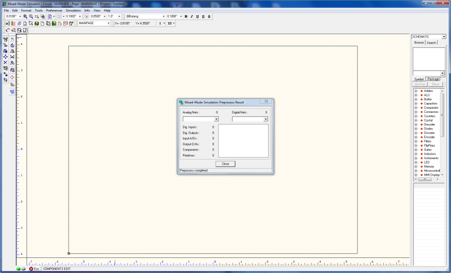
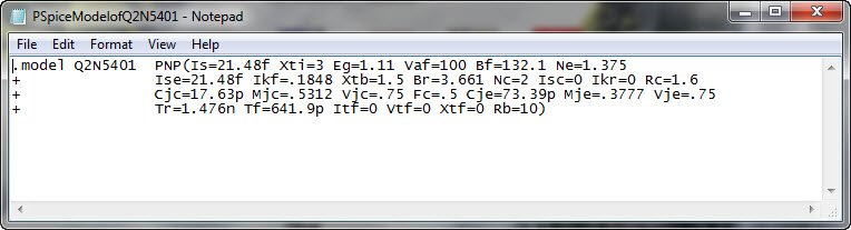
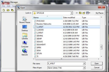
To expand the SPICE model library and learn how to import PSPice models into Proteus, please refer to this article.


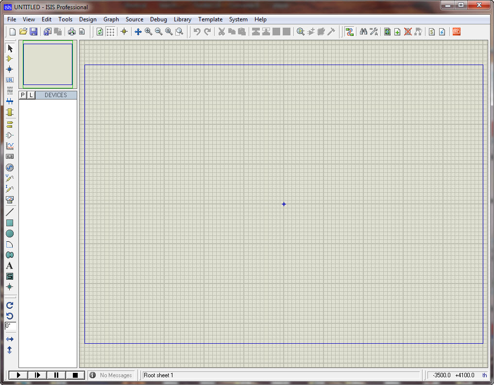
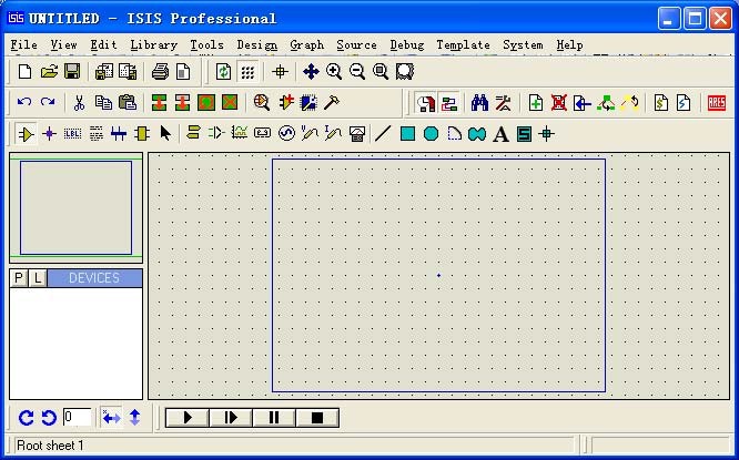
After installing Proteus, run Proteus Professional; the following window interface will appear:


windowinterface


The following is a brief description of each part of the window interface:

1. Schematic Editor window (The Editing Window):

As the name implies, this window is used for drawing schematics. The blue box serves as the editable area where components can be placed. Please note that this window does not have a scroll bar; you can utilize the preview window to adjust the schematic’s visual range.

2. Preview window (The Overview Window):

This window serves two purposes. Firstly, when you are in the component list and select a component, it provides a preview of the chosen element. Secondly, when your mouse focus is on the main schematic editor window (i.e., when you place a component into the schematic editor window or after opening the Schematic Editor window, simply clicking the mouse), it displays a thumbnail view of the entire schematic diagram. Additionally, it highlights a green box within this thumbnail, representing the content currently visible in the main schematic window. By clicking on this green box with the mouse, you can alter its position, consequently adjusting the schematic’s visual range.


Proteuspage28image3


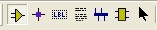
3. Model Selection Toolbar (Mode Selector Toolbar):


Main Modes:


in order from left to right let’s see what the various icons represent:

1 * Select elements (components) ( selected by default )

2 * Place the connection point

3 * place a label ( the bus will be used )

4 * Place text

5 * for drawing bus

6 * for placing subcircuits

7 * for instant editing component parameters ( first click on the icon and then click the element you want to modify )
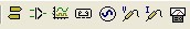
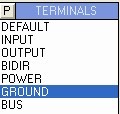


Tools:


1 * terminal interface (terminals): There VCC, ground , output, input and other interfaces

2 * Device Pin : for drawing pin

3 * Emulation chart (graph): used for various analyzes, such as Noise Analysis

4 * recorder

5 * signal generator (generators)

6 * Voltage Probe: to be used when using simulation charts

7 * current probe : Using simulation to be used when using simulation charts

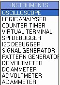
8 * Virtual Instrument :  in the image above, an oscilloscope


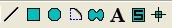
2D graphics (2D Graphics):


1 * Drawing Lines

2 * draw a variety of boxes

3 * draw various circles

4 * draw a variety of arc

5 * draw various polygons

6 * draw various text

7 * draw symbols

8 * paintings origin , etc.


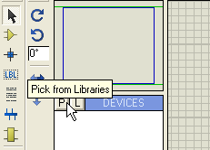
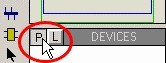
4 . Component List (The Object Selector):

For the selection of components (components), terminal interface (terminals), the signal generator (Generators), simulation chart (graph) and so on. For example , when you select ” Component (Components) “, click the ” P ” button will open the selected component dialog box, select an element after ( click on the ” OK ” after ) , the device will be displayed in the list of elements , later to use this element, just in the component list can be.


5 . Toolbars direction (Orientation Toolbar):

Rotate :


The rotation angle can be an integer multiple of 90 .

Flip:


Flip Horizontal and vertical flip finish . Use: Right-click the component , and then click ( left-click ) the corresponding rotation icon.


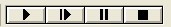
6 . Simulation Toolbar


1 * Run

2 * single-step operation

3 * Pause

4 * Stop


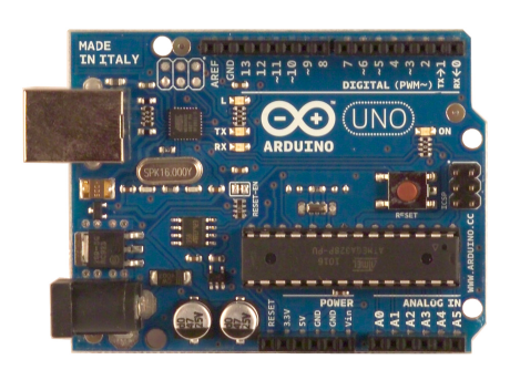
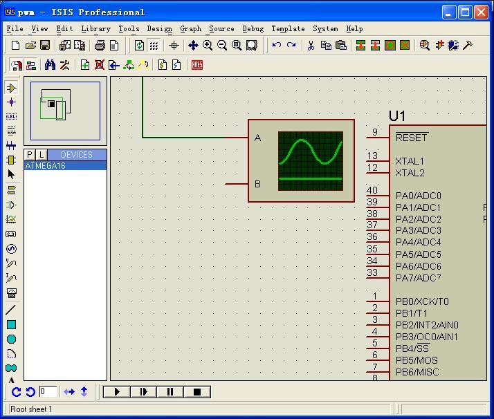
AVR microcontroller simulation example:

We aim to design an AVR driver for an LCD1602 and monitor its data lines using an oscilloscope. It’s worth noting that various compilers generate different file formats. For instance, ICC produces COF files, IAR generates D90 files, and GCC outputs COF and ELF formats. Fortunately, Proteus supports multiple file formats including COF, D90, HEX, and more, making it a versatile platform for our project.

When you launch Proteus Professional, the following window will appear:


Proteus_page30_image2


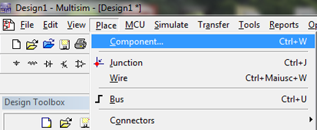
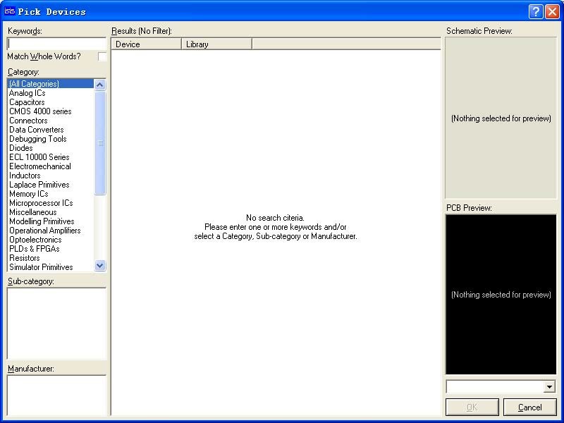
1, Add the components:

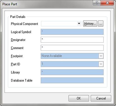
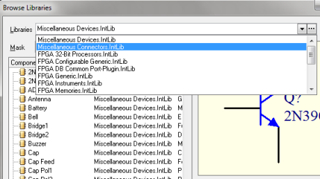
in this case, the ATMEGA16 and LM016L (LCD1602). Afterward, we will add the oscilloscope. Click the “P” button to open the Component dialog box.


Proteus_page31_image2


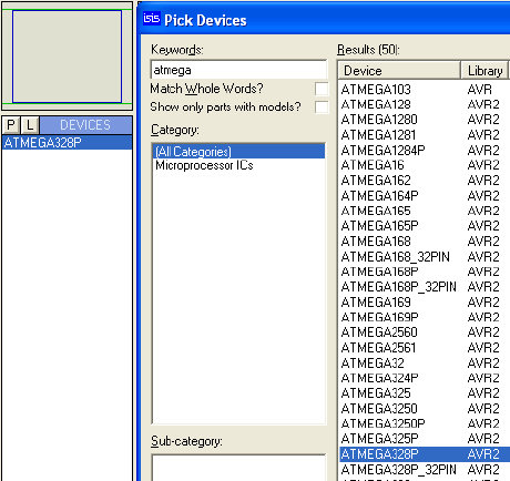
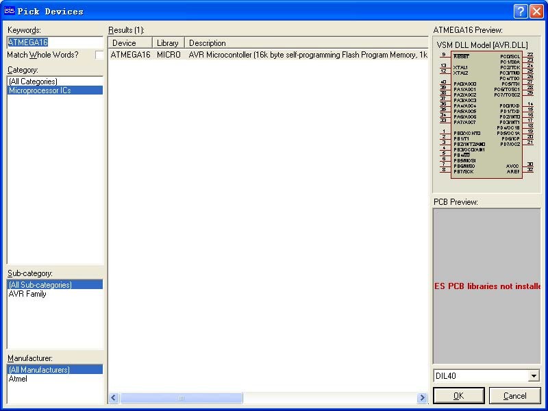
Entering “ATMEGA16” inside the “Keywords” field of the dialog box will yield the following results:


Proteus_page31_image1


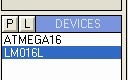
Click “OK” and close the dialog box. Afterward, you will find the components listed in the component list, including ATMEGA16 and LM016L. This concludes the process.


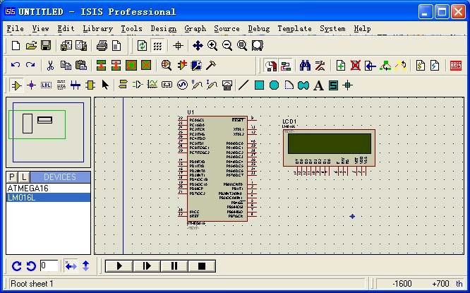
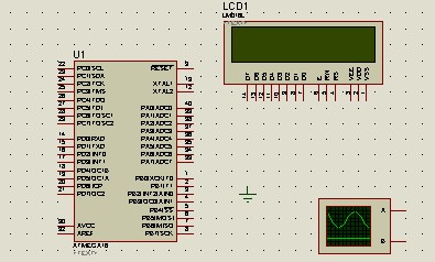
2 Place the components:

In the component list, select “ATMEGA16,” and then in the schematic editor window, left-click to place ATMEGA16 in the Schematic Editor window. Follow the same procedure to place LM016L as well.


Proteus_page32_image5


Click on the ‘terminal interface’ icon, select ‘Ground’ to place the ground reference on the drawing.


left-click to place the “ground” symbol into the Schematic Editor window.


Click on the ‘Virtual Instrument’ icon and select ‘oscilloscope’:


left-click to place the oscilloscope symbol into the Schematic Editor window:


Place the components, making sure to position them inside the blue workarea box.
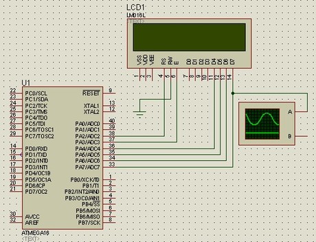


3 . Connection

The terminals of the LCD, VSS, VDD, and VEE do not need connections; they are by default: VSS = 0V, VDD = 5V, VEE =-5V, GND = 0V. Connect the RS, RW, and E terminals, as well as the terminals from D4 to D7, as shown in the picture below.


4 . Add a simulation file.

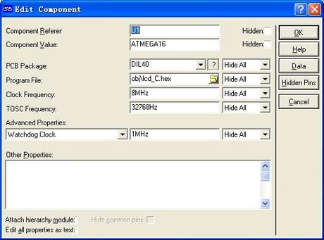
Right-click on ATMEGA16 first, then select ‘Edit Properties.


In the Program File field, click on the File Browser dialog box, locate the ‘lcd_C.hex’ file, click OK to complete the file addition. Set the Clock Frequency to 8MHz, and click OK to exit
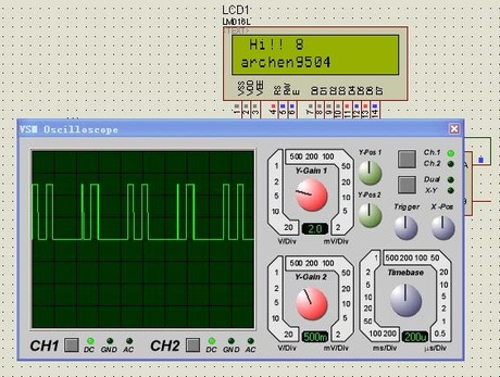


5 . Simulation

Click Start simulation :


Description: The red color of the LCD terminal indicates a high voltage level, while blue represents a low voltage level., gray represents uncertainty level (floating). By running the Debug menu, you can view AVR-related resources.


6 the source code debugging

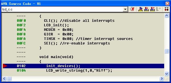
Proteus supports COF file debugging. Make sure to generate this file in your compiler options. Finish the schematic drawing and add the debug files (COF file), then click the icon below:


The AVR Source Code window will appear. If it doesn’t appear in the debugger, navigate to the Debug menu to locate it.


Proteus_page35_image2


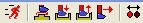
Let’s discuss these icons:


1 * continuous operation , it will exit the single-step debug state , and close the AVR Source Code window

2 * single-step operation , skip directly encountered Functions

3 * single-step operation , will enter its internal encountered Functions

4 * out of the current function , when using 3 * into the internal function , use it immediately on exiting the function returns a function , it should be seen in conjunction with the 3 *

5 * run to the line where is the mouse

6 * Add or remove a breakpoint , the breakpoint is set using the program will stop at the breakpoint.

EDWinXP SPICE Simulation

EDWinXP SPICE Simulation

EDWinXP SPICE simulation caters to a wide range of engineering needs. This versatile toolset comprises several essential components to facilitate the entire electronic project development process.

Schematic Editor The Schematic Editor serves as the frontend for project design, allowing users to create electrical schematics. Components are easily added to the logical diagram using the “Library Browser” or “Library Explorer” functions. Project validation is carried out using circuit simulators like the “Mixed Mode Simulator” and “EDSpice.”

Layout Editor With EDWinXP, project development can start from either the schematic or layout. Users can seamlessly transition between the two using “front annotation” and “back annotation.” The software offers two board-level simulators, “Thermal Analysis” and “Electromagnetic Analysis,” ensuring thorough scrutiny. Additionally, features like the “Signal Integrity Analyzer” help detect high-frequency signal distortions within traces, while the “Field Analyzer” is a graphical tool for studying electromagnetic fields generated by board activation or signal propagation on traces. The Layout Editor also incorporates a 3D concept for visualizing the designed board.

Fabrication Manager This module provides support for various PCB production phases. It enables users to create ground plans, add dimensions and notes, print layout drawings, extract NC data for drilling, and store it digitally or in hard copy. It also facilitates modification, sizing, and printing of drill shapes, PCB modification, Gerber and ASCII file generation, generic machine pick and place file creation, and material list generation.

Library Manager The Library Browser helps users navigate component lists (Parts, Symbols, Packages, Footprints) within available libraries. Various parts can be added to schematics or layouts through drag-and-drop or right-click actions. The Library Explorer lists available libraries, while the Library Editor allows users to add new components or modify existing ones. The incorporation of the 3-Dimension concept in the Library Editor facilitates package and cabinet adjustments, offering multiple perspectives and angles for visualization.

Other Features

  • Conversion Manager: Facilitates library and database format conversions, as well as the import and export of wirelists, schematics, and layouts in various formats.
  • Waveform Viewer: Used to represent simulation results in diagram form for Mix Mode, EDSpice, and Signal Integrity simulations.
  • Subcircuit Adapter: Converts SPICE subcircuits into EDSpice format.
  • Model Parameters Editor: Simplifies the management and creation of model libraries.
  • List Generator: Generates component library and project details lists.
  • Netlist Import and Export: Streamlines the transfer of circuit connection information to and from other software supporting formats like Jedec, Cupl, Xilinx, Altera, and more.
  • Spice Netlist Import: Allows the import of circuit (.cir) and subcircuit (.sbc) files into the system, generating electrical schematics and preserving model parameters for various analyses.
  • Schematic DXF Export: Permits the export of EDWinXP schematics to AutoCAD DXF format.
  • Layout DXF Export: Performs a similar function for layout graphics.
  • VHDL Editor: Introduces VHDL support for describing digital system behavior.
  • Simulation Model Generator: Converts VHDL source files into simulation models.

EDWinXP thus offers a robust and comprehensive suite of tools to facilitate electronic design, simulation, and project management with precision and efficiency.

To delve deeper into the various features and gain confidence  with EDWinXP SPICE simulation, consult this article of video tutorials.


In this article, we’ll study a Series Voltage Regulator schematic circuit using the SPICE simulation software EDWinXP. After the installation, run the program:


Let’s create a new project by selecting ‘Edit Page’ from the MAINPAGE.


It opens a new page


mainpage
TINA Video Tutorials

TINA Video tutorials

Welcome to the dedicated TINA Video Tutorials page, a valuable resource of educational content aimed at helping you master the intricacies of TINA software. In today’s fast-paced technological landscape, the ability to design, analyze, and simulate electronic circuits efficiently is paramount, and TINA Design Suite stands as a powerful tool to meet these challenges. Here, we delve into the world of TINA Video Tutorials, designed to cater to individuals at all levels of expertise.

For those just starting their journey into circuit simulation, these Video Tutorials provide a solid foundation. Beginners can explore fundamental aspects of the simulation environment, gaining insights into creating and analyzing electronic circuits. These tutorials serve as a gentle introduction, gradually acquainting you with TINA’s user-friendly interface and its wide array of features.

Other TINA Video tutorials delve deeper into the intricacies of TINA, such as comparing simulations to real-world measurements. By studying AC analysis and Fourier analysis, you’ll be equipped with the skills to analyze circuit behavior under different conditions. You’ll also learn how to create subcircuits from schematics, enabling modular circuit design and reuse.

For advanced users, TINA Video Tutorials offer a deep dive into the software’s advanced capabilities. You can explore topics like interactive logic gate testing, VHDL circuit design, and PCB development. These advanced features empower you to tackle complex circuit design challenges with confidence, precision, and efficiency.

These selected video tutorials provide step-by-step guidance, ensuring that you not only understand the concepts but also gain practical experience. The goal is to equip you with the tools and insights needed to unlock TINA’s full potential, enabling you to design and analyze circuits with precision and ease.

8051 Microcontroller Course- Embedded C and Assembly Language

TopicVideo
Introduction to TINA Design Suite
Comparison of simulation and real time measurements
Real time transient recording and comparison with simulation
RC transient and AC analysys
Fourier analysis
Active band pass filter
How to make subcircuits from schematics
Test a logic gate in interactive mode
Bus example
Pic flasher circuit
VHDL circuits
Create a simple PCB
Importing SPICE Models into TINA

The Art of Doing: Electronics for Everyone
Start designing, building, and playing with your own circuits today!!

Importing PSpice models into TINA

Importing PSpice models into TINA

Welcome to our comprehensive guide on “Importing PSpice Models into TINA.” In the world of electronic circuit design and simulation, the ability to seamlessly integrate models from different simulation platforms can significantly enhance your capabilities. In this article, we will walk you through the process of importing PSpice models into TINA, a powerful simulation tool. To illustrate this procedure, we will use the example of a 3-stage BJT amplifier simulation, demonstrating how to effectively bridge the gap between PSpice and TINA. By the end of this tutorial, you’ll have the knowledge and skills needed to effortlessly incorporate PSpice models into your TINA simulations, expanding your design possibilities and streamlining your workflow. Let’s delve into the world of cross-platform simulation integration and discover how to make the most of these versatile tools.


basicamplifierexample


Right-click on one transistor of the differential pair and select ‘Properties…


the Properties window appears, click the ellipsis button and the Catalog Editor window pops up


the table view appears because the 2N5104 PNP transistor is a component of a *.cat library, a TINA’s CATalog files that contains the built-in TINA components and the built-in semiconductor catalogs


First and foremost, we aim to demonstrate how to replace the built-in 2N5101 with the following PSpice model of an equivalent PNP transistor and incorporate it into an existing .lib library. The specific model of the PNP transistor may vary, but its identity is not critical for the context of our example:


pspicemodelofq2n5401


Open the Library Manager tool in the TINA suite


and select, for example, the s_AFBJT.lib library file


ViaDesigner Video Tutorials

TopicVideo
Creating Tutorial Designs within ViaDesigner
Creating Simulation Models with the Datasheet Curve Tracer in ViaDesigner
“Do The Harlem Shake” Circuit to Detect Low Frequencies Audio Signals
Creating a VHDL model in ViaDesigner
Importing & Processing Oscilloscope Data in ViaDesigner Simulations