
Now we can run Spice Opus program (Windows)

Let’s examine a BJT amplifier in the common emitter configuration, featuring an emitter capacitor as shown in the image below. (Please note that the schematic is not created using SPICE OPUS, as it lacks a built-in schematic program.)

We need to edit a .cir file that outlines this circuit. Let’s launch a text editor, such as Notepad for instance, and commence describing the circuit. The netlist for the above example is as follows:
BJT common emitter configuration with emitter capacitor
* Biasing Supply
vcc vcc 0 dc 12
* Input Signal Source
vin in 0 dc 0 ac 1mv 0 sin(0 1mv 10kHz)
* Biasing Resistors
r1 vcc b 9.8k
r2 b 0 2.2k
re e 0 300
rc vcc c 900
* Coupling Capacitors
cin in b 4.7uf
cout c out 10uf
* Emitter Capacitor
ce e 0 100uf
* Load Resistance
rout out 0 47k
* Transistor
q c b e BC368
* model of Transistor BC368
.model BC368 NPN(Is=14.06f Xti=3 Eg=1.11 Vaf=100 Bf=187.6 Ise=137.2f
+ Ne=1.468 Ikf=4.103 Xtb=1.5 Br=4.541 Isc=44.13f
+ Nc=1.471 Ikr=1.701 Rc=91m Cjc=52.24p Mjc=.3333 Vjc=.5 Fc=.5
+ Cje=156p Mje=.3333 Vje=.5 Tr=10n Tf=964.8p Itf=595.3
+ Xtf=1.001K Vtf=10)
.end
It is important to rename the file from *.txt to *.cir. For this example, let’s name it BJTcommonemitter.cir. Place the file in the installation directory, in our case, C:\Spiceopus. Now, let’s proceed to load the circuit’s netlist into the simulator using the ‘source’ command:
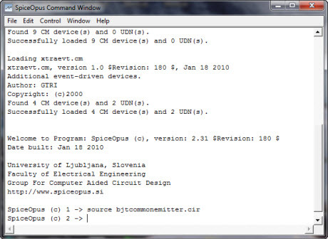
The filename is not case-sensitive. The ‘tran’ command is used to perform a transient analysis from 0 to 1000us with a 10kHz sine wave input, utilizing a step size of 1us.
The analysis results can be visualized using the ‘plot’ command. In this case, we define ‘vout,’ ‘vin * 50,’ the labels for the x and y axes, and time in milliseconds.

