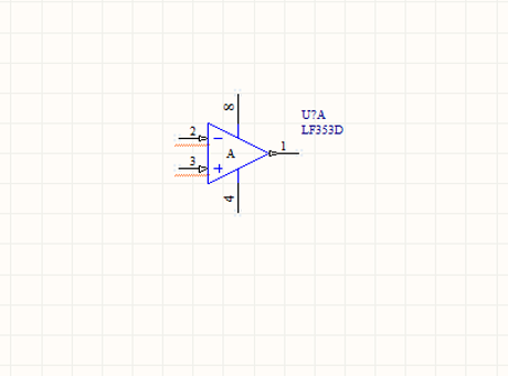
Let ‘s place the device, right click on it, and select “Properties…”
the “Component Properties” window pops up, type U1 in “Designator” field:
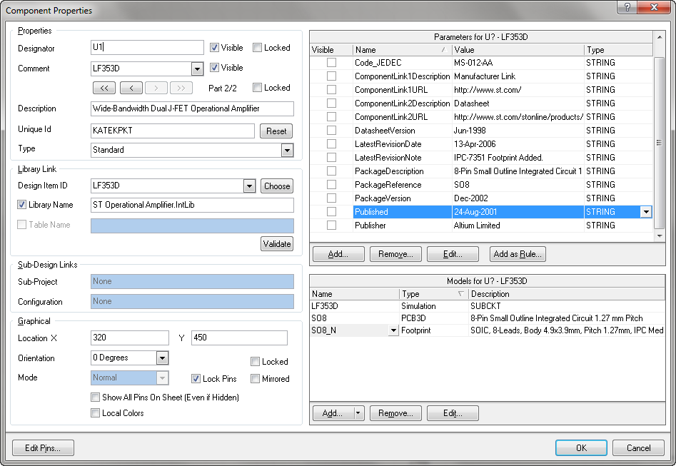
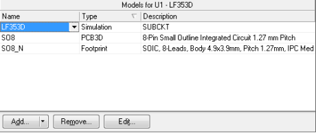
If you want to examine the SPICE simulation model, let’s choose the device in the Models panel and click on “Edit”.
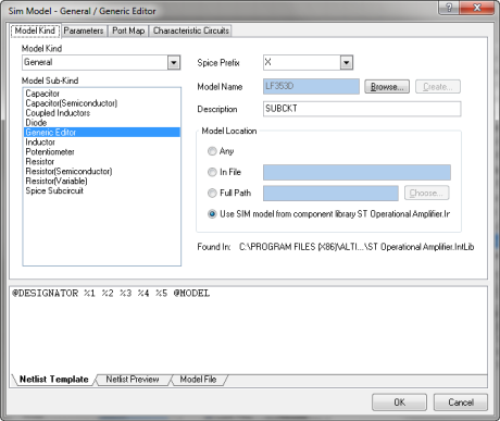
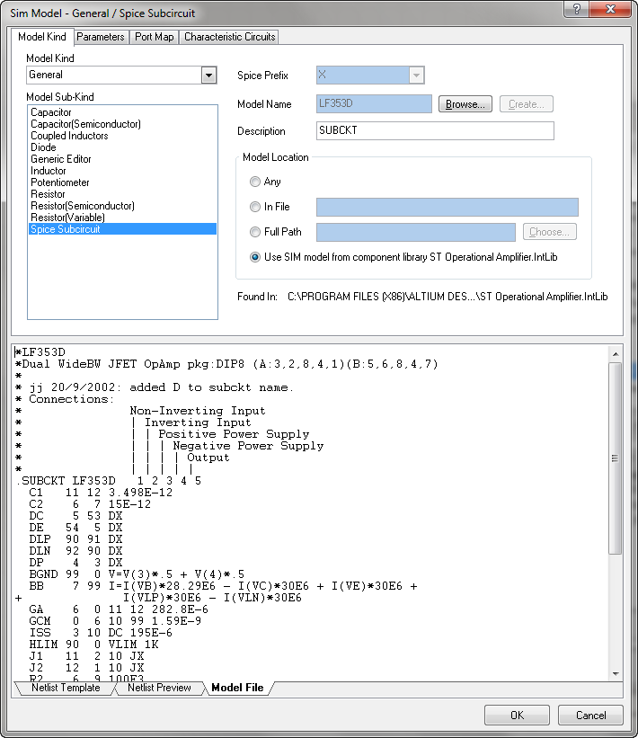
select “Spice Subcircuit” from Sim Model window and click on the “Model File” tab to display the contents of the model file
now we can see the syntax SPICE description of simulation model
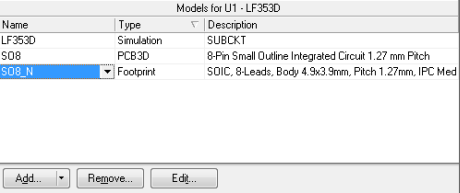
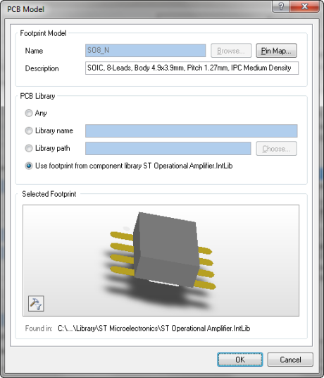
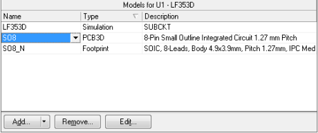
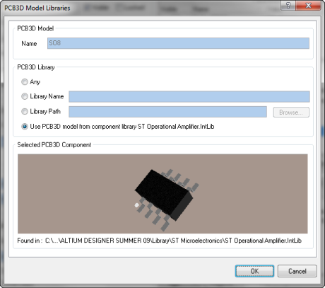
From the panel Models of the “Component Properties” window, we can easily see the PCB 3D model of the device, select S08 and click on “Edit…” button
similarly, for the footprint model