Here are some example of circuits simulation based on PSPICE SIMULATION TOOL
1:Simulation of Output characteristics of NPN BJT in common configuration.
PSPICE coding:
*output characteristics of NPN BJT in CE configuration
IB 0 1 DC 1mA
VCE 2 0 DC 12V
Q1 2 1 0 Q2N2222A
.MODEL Q2N2222A NPN (IS=2.105E-16 BF=173 VA=83.3V CJE=29.6PF CJC=19.4PF TF=489.88PS TR=4.9NS)
.DC VCE 0V 10V 0.02V IB 0A 1mA 200U
.PROBE
.OP
.END
GRAPHICAL ANALYZER:

CONCLUSION:
* From above graph we concluded that in the saturation region the change in base current IB does not produced any change in collecter current.
*In the cutoff region small amount of collecter current flows when IB=0. Basicaly this is leakage current.
*In active region for small values of base current IB the effect of collecter voltage VCE over collecter current IC is small and for large value of base current its effect increases.
2: Study of transient and frequency response of PNP BJT AMPLIFIER in CE configuration.
PSPICE CODING:
*study of frequency n transient response of CE configuration PNP BJT amplifier
.TRAN/OP 50US 2MS
*.AC DEC 10 1HZ 10KHZ
.OP
VIN 1 0 AC 10MV SIN(0MV 10MV 1KHZ)
VCC 0 7 DC 15V
RS 1 2 500
R1 7 3 47K
R2 3 0 5K
RC 7 4 10K
RE 5 0 2K
RL 6 0 20K
C1 2 3 10UF
C2 4 6 10UF
CE 5 0 10UF
Q1 4 3 5 0 QM
.MODEL QM PNP(IS=2E-16 BF=50 BR=1 RB=5)
.PLOT TRAN V(4) V(6) V(1
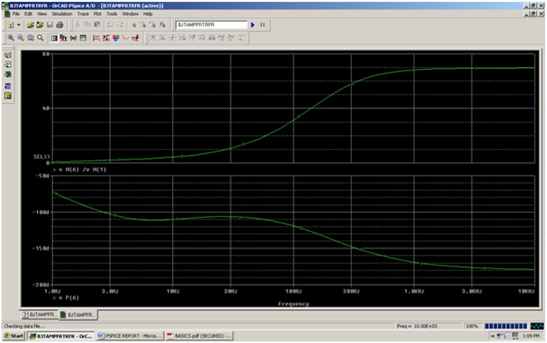
.PLOT AC VM(6) VP(6)
.PROBE
.END
GRAPHICAL ANALYZER FOR TRANSIENT RESPONSE:
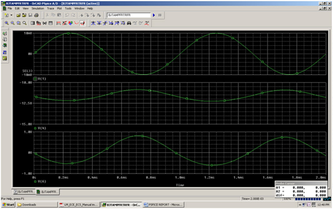
GRAPHICAL ANALYZER FOR FREQENCY RESPONSE: