3. Transformer for Flyback converter: Calculation example.
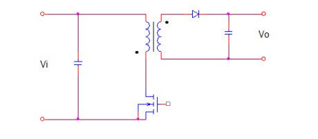
Required Data:
Output power: 405W
Vo output voltage: 27 V
I output current: 15 A
Grid voltage VR: 220 Vac +- 20%
Grid frequency fr: 50Hz
Switching frequency f: 100KHz
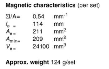
1. From the required data, with the aid of Table 1 is detected in ETD49 – N67 the ferrite suitable for the realization of the transformer. From the catalog we obtain the magnetic properties below.
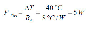
2. Through the Table 2 identifies that the maximum allowable temperature rise for ferrites made with materials N67 is 40 °C.
3. Table 3 identifies the value of the thermal resistance of the transformer for the ETD49 in 8 °C/W.
4. the maximum power dissipation for the losses in the ferrite and copper in the windings is calculated through the (0.2)
5. The minimum input voltage value is calculated through the (0.3)
Known Data:
Grid voltage: Vr = 220V +-20% VAC
Grid Frequency: fr = 50Hz
Max Peak Voltage: VRi max = (220 + 220*20/100) *SQRT(2) = 373V
Min Peak Voltage: VRi min = (220 – 220*20/100) *SQRT(2) = 249V
Estimated Data:
Efficiency coeffcient 0.8
Input Power : Pi = 405W/0.8 = 506W
Value of Input Capacitor: Ci= 1000uF
Determination of the minimum input voltage

We can reduce of about 10V the calculated value to take account of the voltage drop due to the resistance of the winding and to the diodes at maximum power.

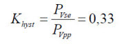
6. Distribution of power lost from the (0.5)

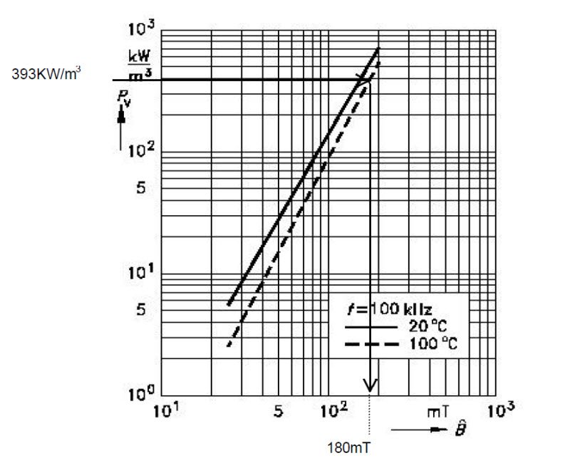
7. Calculation of power lost in specific volume for the ferrite ETD49 from the(0.6).
Known Data:
Power loss in square wave:

Losses single-ended vs push-pull
Considering that the volume of a pair of ferrites ETD49 is 24100mm^3, the loss of specific power per unit volume will be:

From the diagram below, for the material chosen N67 Pv = f (f) for f = 100KHz and T = 100 ° C we get a delta Bmax of about 180mT:
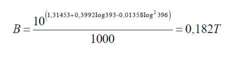
8. Determination of the maximum permitted flux delta Bmax as a function of the losses in the ferrite.
With the (0.7) we can determinate also by analytical way the maximum value allowed for the induction, that for material N67 at 100 ° C and with a frequency of 100KHz is:
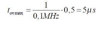
9. Calculation of the number of turns in the primary through the (0.8) and (0.9).
Duty Cycle Tv= 0.5
Max on time:

10. Estimation of resistance in Ohm of the primary winding through (0.10)

Duty Cycle: tv = 0.4
Maximum closing time:

Figure 3 – Parameters of support for ETD49 FERRITES and Accessories, Siemens Matsushita Components.
11. Calculatiopn of the number of secondary turns with (0.12).
To calculate the number of secondary turns is necessary to identify a good approximation of the real value of the
voltage applied to the primary and the secondary voltage required. For this reason, are taken into account for the
voltage drops to the diode of the secondary winding, estimated at Vd = 2V.
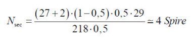
Obtaining a non-integer number of turns, it is approximated to the nearest integer. As alternative, in an interactive way, we might recalculate the number of turns in the primary so that the number of secondary turns is an integer number. Consider, however, that the number of turns in the primary is inversely proportional to the flux, to avoid that this increases, the number of turns in the primary can be only increased.
12. Calculation of the section of the windings through (0.13).

(0.24)

(0.25)
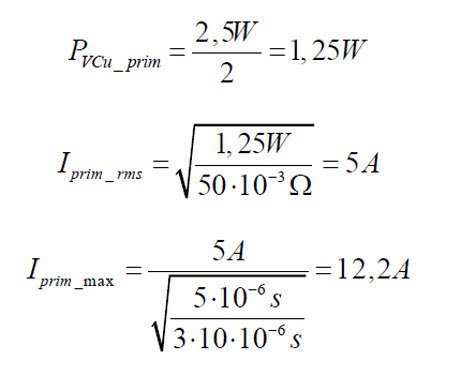
13. Calculation of the primary current with (0.17), (0.18), (0.19).
The primary current is assumed triangular in shape. The copper losses are considered to be equally divided between primary and secondary.
14. Calculation of the maximum allowed inductance of the primary from (0.20).

15. Calculating the maximum value of the inductance factor AL through the (0.21).

If the ratio between the thickness of the winding and its width is low, the value of AL can be reduced; Furthermore the tolerance in the value of AL for the type of ferrite choice, encoded as G class , is +- 2%.
Considering 106nH as the maximum value we can determine the average value by estimating a maximum deviation of AL of 10% (empirical data):

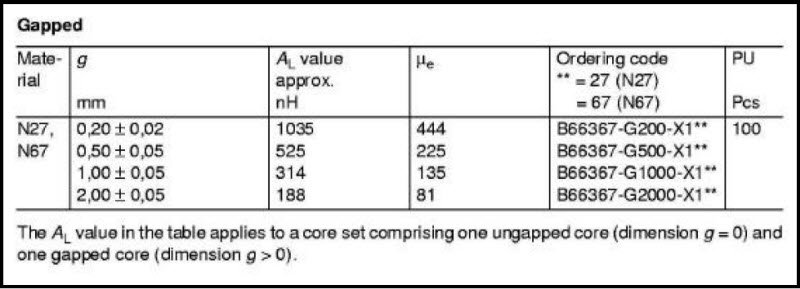
16. Determination of the value of the air gap from (0.22).
Known the value of AL we can find the value of air gap. From the catalog we can find the half-core with gap close to the value of AL calculated, or estimate its value by the formula. The value can be obtained by combining
the half-cores with different gap values. This represents the best solution, when it’s possible, to contain the leakage flux and the parasitic inductance. Otherwise the value of air gap required is achieved by interposing
shims between the half-cores.
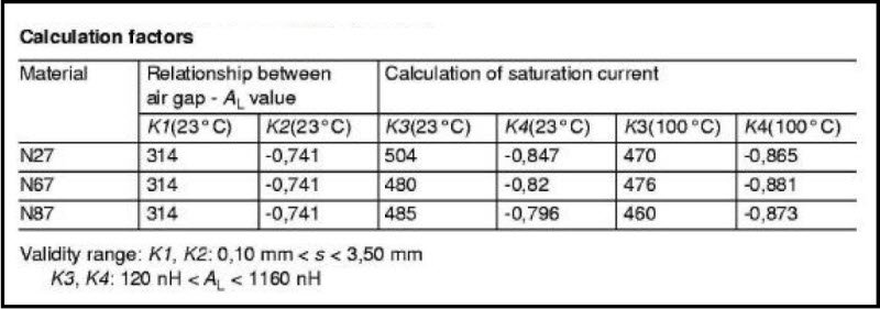

The (0.22) reminds us that the validity of the formula is restricted to gap values between 0.10 and 3.00 mm, then most likely the value of 5.02 mm is not suitable for AL of 95nH. In these cases it is necessary to measure the value of the primary inductance and adjust the gap to obtain the calculated value.
17. Maximum power transferred by the transformer (0.23).
