2. Simplified calculation of the transformer
What follows is a simplified example of design of the transformer switching power supplies both for Flyback and Forward type. The procedures and formulas are taken from Application Note contained in FERRITES and Accessories Siemens Matsushita Components AG published by 1994. The whole calculation procedure follows this guideline:
1. known the type of the power supply, the demand for output power and the switching frequency, let’s choose the ferrite suitable (for example by consulting Table 1).
2. Identification of the maximum permissible temperature rise delta T for the type of material chosen (see Table 2).
3. Determination of the overall thermal resistance of the transformer (see table 3 or via the (0.1))

(0.1)
where
Rth : thermal resistance in °C/W
A: surface of the transformer in cm^2
4. Calculation of the maximum power loss dissipated from the transformer into its components, copper and ferrite, so that the temperature does not exceed the threshold identified in step 2.

(0.2)
where
PVtot: Total power dissipated by the transformer in W
delta T : maximum overtemperature permitted in °C
Rth: thermal resistance in °C/W
5. Identification of the minimum value of voltage applied at the input.
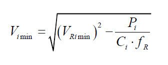
(0.3)
where
Vimin: Minimum input voltage in V (dc)
VRimin: Minimum voltage of electrical network in V (dc)
Pi : Maximum absorbed power input in W
Ci : Input filter Capacitance in F
fr : Frequency of electrical Network in Hz
6. Distribution of lost power.
It is estimated that the losses calculated with (0.2) equally distributed between the ferrite and copper

(0.4)

(0.5)
where
PVtot: Total power loss dissipated by the transformer in W
Pvfe: Power loss in the ferrite in W
Pvcu: Power lost in the copper in W
7. Calculation of power loss in specific volume for the ferrite choice.
The values of specific power lost indicated in the manual refer to measurements made with a sinusoidal
waveform and with full cycle of magnetization (eg push-pull configuration). Therefore, to determine the losses with
square wave and single-ended configuration, you must use the correction factors (KForm, Khyst).
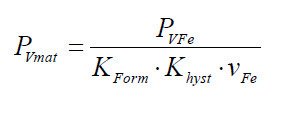
(0.6)
where
PVmat: Specific Power lost in volume in kW/m3
PVfe: Power loss in the ferrite in KW
Vfe: Ferrite volume in m3
Kform: Form factor of 0.8 for square wave, 1 for sine wave
Khyst: Coefficient of hysteresis vs. single-ended push-pull = 0.33
8. Determination of the maximum permitted flux delta Bmax as a function of the losses in the ferrite.
From the graphs shown in the catalog quoted relative to the power lost as a function of the frequency is obtained
the maximum flux permitted. The following chart is an example relating to the material N67 Pv = f (B) for
f = 100KHz and T = 100 ° C.

Figure 2 – Pv = f (f) material N67 @ T = 20 and 100 °C.
as alternative, with good approximation, we can use the following formula to calculate the value of maximum
induction B at 100 ° C for material N67 as a function of the losses expressed in kW/m3 for switching frequencies
of 25; 50,100,200 KHz:

(0.7)
where
B: Maximum value of permitted induction in T
PVmat: Power lost in specific volume in kW/m3
25KHz 50KHz 100KHz 200KHz
a : 1,65551 1,5315 1,31453 1,06514
b : 0,31752 0,3151 0,2992 0,4334
c : 0,01249 0.0095 -0,01358 -0,01514
9. Calculation of the number of turns in the primary.
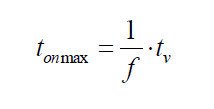
(0.8)
where:
tonmax: Maximum period of closure in s
tv: Duty Cycle
f: Switching frequency in MHz
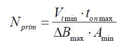
(0.9)
where
Nprim: Number of turns in the primary
Vimin: Input voltage minimum V (dc)
tonmax: Maximum period of closure in us
Bmax: Maximum flux in T
deltamin: Minimum area of ferrite in mm^2
10. Estimation of DC resistance of the primary winding.
In estimating the value of the resistance of the primary winding are used of the average values given
in the documentation of the support (coil formers) relatively to the size of the ferrite used. The empirical
formula that allows us to estimate the resistance of the winding is:

(0.10)
where:
Rt_prim: resistance primary winding (20 °C + delta T) in Ohm
N: number of turns
ln: average length of a loop ( from catalog) in m
rhoCu: specific resistivity of copper at 20 °C in Ohm mm2 / m (0.0172)
An: cross-sectional area of support usable ( from catalog) in mm^2
fCu: factor arrangement of copper (0.25)
alphaCu: temperature coefficient of copper (4.3 * 10-3 / °C)
delta T: temperature increase above 20 °C
11. Calculation of the number of secondary turns.
In calculating the number of secondary turns is necessary to identify a good approximation of the real value of the voltage applied to the primary and the secondary required voltage . For this reason, the voltage drop of the diode rectifier connected to the secondary winding is taken into account , estimated at Vd = 2V, and the voltage drop
to the leads of the switching element (transistor or MOSFET) estimated VTR = 10V.
Forward

(0.11)
Flyback

(0.12)
where:
Ns: number of turns in the secondary
Vo: DC voltage required on output in V
Vd: estimated voltage drop across the diode rectifier on output in V
tv: Duty Cycle
Nprim: Number of turns in the primary
Vimin: minimum Input voltage in V (dc)
VTR: voltage drop across the switching element in V
12. Calculation of the section of the windings

(0.13)
where:
ACu: estimated Section winding in mm2
AN: sectional area of usable support (from catalog) in mm^2
fCu: arrangement Factor of copper (0.25)
N: Number of turns
13. Calculation of the primary current of the transformer
The calculation of the primary current of the transformer is done with different procedures depending on the type of circuit.
| Forward | Flyback |
| The trapezoidal current in the primary is approximated as rectangular.It’s taken into account the magnetizing current deltaImag. | The primary current is assumed triangular.The copper losses are considered to be equally distributed between primary and secondary. |
 (0.14) |
 (0.17) |
| where:Lprim: primary inductance in HNprim: Number of turns in the primaryAL: inductance factor H/spire^2 (see catalog) | where:PVcu_prim: copper losses in the primary in WPVcu_sec: copper losses in the secondary in WPVCu: Total losses in the copper in W |
 (0.15) |
 (0.18) |
| where:delta Imag: Magnetizing current in AVimin: minimum Input voltage in V (dc)tonmax: Maximum period of closure in sLprim: primary inductance in H | where:Iprim_rms: Maximum current rms to the primary in APVcu_prim: copper losses in the primary in WRt_prim: primary resistance at 100 °C in Ohm |
 (0.16) |
 (0.19) |
| where:Iprim_max: Maximum current in the primary in AIO: Maximum output current in A (dc)Nsec: secondary Spire numbersNprim: primary Spire numbers
delta Imag: Magnetizing current in A |
where:Iprim_max: Maximum current in the primary in AIprim_rms: Maximum current rms to the primary in Atonmax: Maximum period of closure in s |
Additional considerations for the type Flyback
14. Calculation of the maximum inductance of the primary winding.

(0.20)
where:
Lprim_max: maximum Inductance to the primary in H
delta Bmax: Maximum flux in T
Nprim: Number of turns in the primary
Amin: Minimum area of ferrite in m^2
Iprim_rms: Maximum current rms to the primary in A
15. Calculating the maximum value of the inductance factor AL.
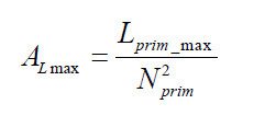
(0.21)
where:
Almax: Maximum value of the inductance factor in H/spire2
Lprim_max: maximum Inductance to the primary in H
Nprim: Number of turns in the primary
16. Determination of the value of the air gap.
The determination of the value of the air gap can be done by consulting the catalog. For each type of ferrite are indicated the electrical and mechanical parameters, in addition to the indication of the available half-cores with air gap and the relative values of AL obtainable.
As alternative, if the value of AL requested is not available, it is possible to approximate the required value by inserting shims between the half-cores until it reaches the value of air gap required. This value can be estimated with the following formula valid for materials N27, N67, N87 for 0.10 <s <3.00 mm:
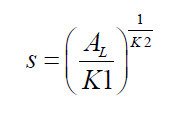
(0.22)
where:
s: value of the air gap in mm
AL: value of inductance factor in nH
K1, K2: specific constants of the core (catalog)
Note: If the air gap is obtained with the introduction of shims between the two E half-cores, consider that the magnetic circuit is interrupted in two points, actually are three, but a point with section S (center column), and two with section S/2 (external columns), then the size of the shim to be inserted should be half that calculated.
17. Maximum power transferred by the transformer

(0.23)
where:
Pmax: Maximum transferable power in W
Iprim_rms: Maximum current rms to the primary in A
Lprim_max: Maximum Inductance to the primary in H
f: Frequency in Hz
